
Digital Car Voltage Meter

The Car Voltage Gauge circuit consists of three primary components: an Analog to Digital Converter (ADC), a Display/Decoder Driver, and a power regulation system. The ADC, specifically the CA3162E, is responsible for sampling the analog voltage output from the vehicle's electrical system. This sampled voltage is then converted into a digital representation, which is subsequently processed by the CA3161E Display/Decoder Driver. The output from the driver activates the seven-segment displays through a series of transistors (Q1 to Q3), which serve as switches to control the illumination of each display segment.
Power for the circuit is supplied by the vehicle's battery, with a dedicated 5-volt voltage regulator ensuring that the ADC and driver operate within their specified voltage range. The circuit includes a 10µF capacitor that acts as a charge reservoir, stabilizing the voltage readings by smoothing out fluctuations in the input voltage from the vehicle. The ADC reads the voltage across the capacitor, converting it to a decimal value that reflects the vehicle's operating voltage.
The display system is designed to multiplex three seven-segment displays, sequentially illuminating each one to show the corresponding voltage reading. This multiplexing technique not only reduces the number of required connections but also minimizes power consumption.
Adjustment features are incorporated into the design to enhance accuracy. Two potentiometers, labeled "Zero Adj." and "Gain Adj.", allow for fine-tuning of the displayed voltage reading. These adjustments are critical for ensuring that the voltage gauge provides precise measurements, which can be verified using a calibrated multimeter.
Additionally, the circuit includes optional indicators in the form of two LEDs. These LEDs can signal the power status of the gauge or illuminate a cut-out display that indicates "Volts." The cut-out display can be constructed from a plastic module featuring a thin cover with the word "Volts" etched into it, allowing the LEDs to shine through when activated. This feature adds a visual element to the circuit, enhancing usability and readability in various lighting conditions.The Car Voltage Gauge is based on 3 parts. The input circuit is an Analog to Digital Converter (IC2 CA3162E). The purpose of this chip is to sample an analog voltage and convert it to a decimal value which is read by a Display/Decoder Driver (IC1 CA3161E). This chip will turn each seven segment display on through the driver transistor Q1 - Q3. The power is derived from the car and is converted to 5 volts by the 5 volt regulator. The circuit works as follows: The 10uf capacitor is charged up by the cars voltage. Its value is then read by IC2 and a decimal value of that voltage is provided to IC1 which multiplexes the three display units.
Each display is turned on sequentially with its appropriate value displayed. The transistors Q1 through Q3 control the drive to each seven segment display. By monitoring the cars voltage with an accurate multimeter you can adjust the "Zero Adj." pot and the "Gain Adj." pot for accurate readings. LED 1 and 2 are optional. They can be used to indicate power on or can light up a cut out display that says "Volts". This can be made by a plastic module that has a thin plastic cover on it with the word "Volts" cut into it.
The LED's would be mounted inside the module. 🔗 External reference
Related Circuits
The circuit is connected in parallel with the output of a power amplifier and provides the signal level from the output. By adjusting the resistance R1 in the input circuit, the power indication can be adapted to the resistance...
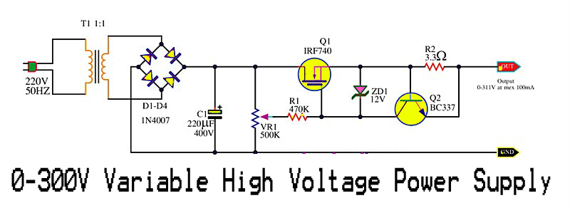
This is a variable high voltage DC power supply circuit that allows for customization of the output voltage ranging from 0 to 311V DC. It includes a current limit protection feature set at approximately 100 mA. The power MOSFET...
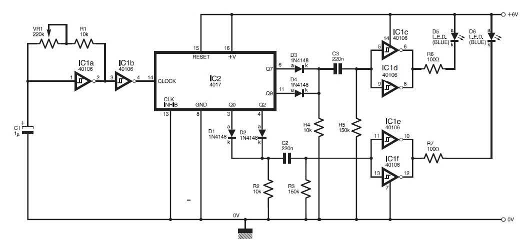
This circuit simulates the flashing lights of a police car, similar to those seen on British police vehicles. The operational amplifier IC1a functions as a square wave oscillator, with an adjustable frequency controlled by the variable resistor VR1 to...
To measure the frequency response of the e-meter, a Wien Bridge oscillator, oscilloscope, and single-ended power supply were used. The oscillator employs a TL074 quad op-amp, utilizing only two of the op-amps. Op-amps typically require two power supplies, one...
I have received countless emails asking for a circuit to tell the user which car won in a pine car (also called Pinewood Derby, Cub Car, Scout Car, etc.) race. This simple circuit takes care of the guesswork, lighting...
The sphygmomanometer can be categorized into two main types: the mercury sphygmomanometer and the electronic sphygmomanometer. The mercury sphygmomanometer is known for its accuracy, but it requires professional operation and is prone to observational errors due to subjectivity. Additionally,...