
vu meter 4

The described circuit functions as a signal level indicator for a power amplifier output. It is designed to monitor the output signal level while ensuring that it does not interfere with the normal operation of the amplifier or the connected loudspeaker. The parallel connection allows for the measurement of the output signal without disrupting the flow of power to the loudspeaker.
The key component, R1, serves as a variable resistor or potentiometer that enables the user to fine-tune the sensitivity of the signal level indication. By changing the resistance value of R1, the circuit can be adapted to different loudspeaker impedances, ensuring accurate readings across various setups. The circuit may also include additional components such as capacitors for filtering out noise and diodes for protection against voltage spikes.
The output signal from the circuit can be fed into a display unit or an analog meter, providing real-time feedback on the power level being delivered to the loudspeaker. This feature is particularly useful in audio applications where maintaining optimal performance is crucial. Overall, the circuit is an essential tool for audio engineers and technicians who require precise monitoring of amplifier output levels.The circuit is placed parallel with the exit of power amplifier and us gives the level of signal ,from output. Changing resistance R1, in the input circuit, we adapt the indication of power, in the resistance of loudspeaker, that we use..
🔗 External reference
Related Circuits
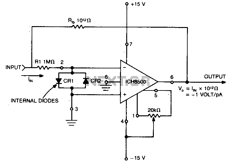
A highly sensitive picoammeter (−1 V/pA) utilizes an amplifier configured in the inverting or current summing mode. It is crucial to eliminate stray currents from entering the current summing mode. The circuit stabilizes to within 1% of its final...
This simple circuit is based on the well-known integrated circuit LM3915. The main characteristic of this integrated circuit is its ability to manage 10 Light Emitting Diodes (LEDs) in a logarithmic scale, with a 3dB difference between the LEDs,...

Construct a digital multimeter capable of measuring DC and AC voltages up to 100V and DC and AC currents up to 1A. The circuit will be powered by a 9V battery. The design incorporates a modified voltmeter to suit...
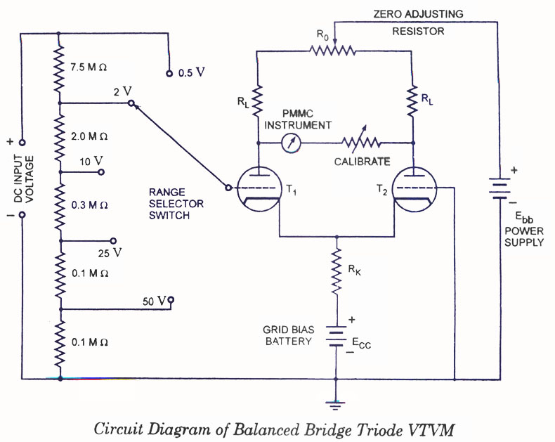
Voltmeters can be utilized for measuring both direct current (DC) and alternating current (AC) voltages and are widely used. These voltmeters are available in two types: vacuum tube and transistorized. In the vacuum tube version, two identical triodes, T1...

This design circuit is a tachometer circuit based on the LM2907 integrated circuit, which can provide zero-crossing data to a digital system. At each zero crossing of the input signal, the charge pump alters the state of capacitor C1...

One of the goals of Movable Party is to provide an interactive experience for audiences and participants. Power will be generated from a hub motor attached to the rear wheel of each bike, with the speed of the rear...