
Police Car Lights with LEDs

This circuit utilizes a combination of integrated circuits and passive components to create a realistic simulation of police car lights. The square wave oscillator (IC1a) is central to the design, where the frequency can be adjusted to match the desired flashing rate. The buffering stage (IC1b) ensures that the square wave signal is stable and strong enough to drive subsequent components without distortion.
The decade counter (IC2) plays a crucial role in generating the alternating double pulses necessary for the strobe effect. By using outputs Q0/Q2 and Q7/Q9, the circuit can produce a sequence of pulses that mimic the rapid on-and-off behavior of actual police lights. The diode ORing method allows for the combination of these outputs, ensuring that both pulse signals contribute to the final output.
The pulse differentiation stage, formed by capacitors C2 and C3 in combination with resistors R3 and R5, is essential for controlling the pulse width. This configuration allows for precise timing adjustments, resulting in the short 30 ms pulse duration that enhances the visual impact of the flashing lights. The output drivers (IC1c and IC1f) are responsible for delivering the final signal to the LEDs, ensuring they illuminate brightly and effectively.
The choice of hyper-bright blue LEDs (D5 and D6) is critical for achieving a realistic appearance. These LEDs should be selected based on their luminosity and color quality, as they directly influence the effectiveness of the simulation. The power supply, consisting of a 6V camera battery or four AAA cells, is designed to be compact yet capable of sustaining long operational periods, making the circuit practical for various applications.
Overall, this circuit design successfully replicates the characteristic flashing of police car lights through careful selection of components and thoughtful configuration, resulting in an engaging visual display. Adjustments via VR1 allow users to customize the effect further, making it versatile for different scenarios.This circuit is used to simulate the police car lights by alternating flashing strobes seen on British police cars. The IC1a forms a square wave oscillator having adjustable frequency with VR1 to give the best effect.
This square wave is buffered by IC1b and in turn drives the decade counter IC2. Outputs from the counter Q0/Q2 and Q7/Q9 are in tur n diode ORed to give alternating double pulses. C2 and C3 with R3 and R5 differentiate the pulse time in conjuction with the output drivers IC1c and IC1f. This produces a short pulse (30 ms) which enhances the flashing effect and adds to the illusion. The output drivers in turn drive a pair of hyperbright blue leds D5 and D6. It is worth spending a little extra on using realy bright leds if the best effect is to be obtained. A 6 V camera battery or four AAA cells gives a long life in a small package. In use adjust VR1 to give the best effect. 🔗 External reference
Related Circuits

A main component along with a 2N3055 transistor and an IC TL072 is utilized in the pulse oscillator generator. The output voltage reaches +50V and -50V, providing a current of 2A to 3A. The circuit employs a 2N3055 transistor, which...
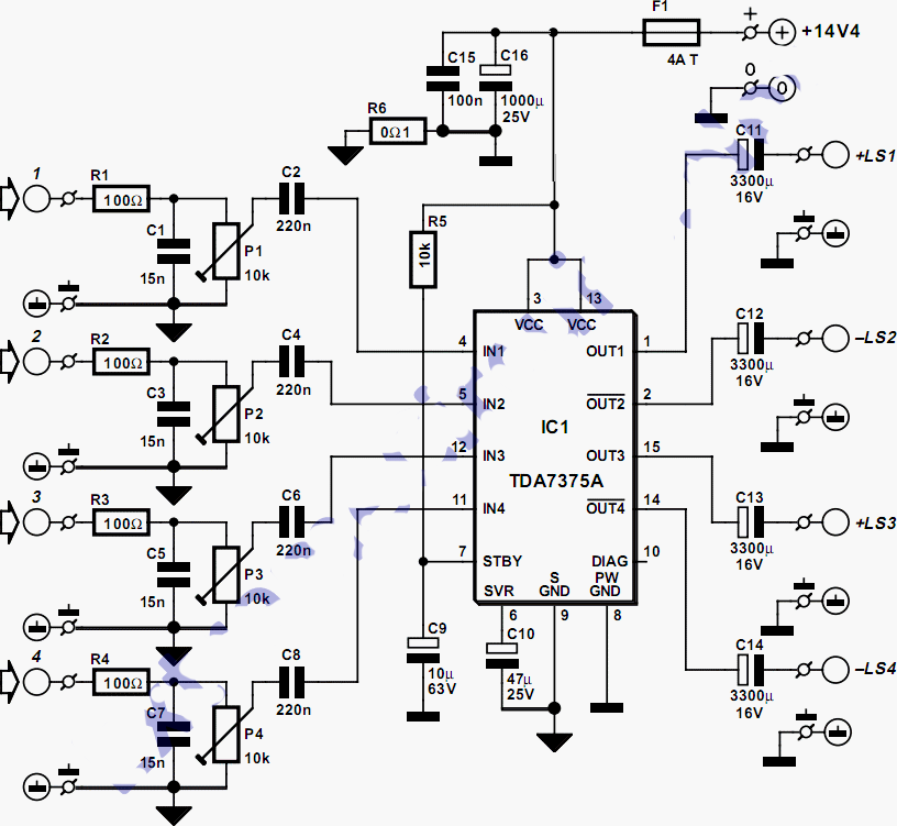
This quad amplifier is designed primarily for automotive use but can also be applied in various medium-power scenarios. The TDA7375A is suitable for situations requiring a reasonable amount of audio power with a relatively low supply voltage. It is...
Typically, a charged lead-acid battery and a power inverter are utilized to ensure a well-organized holiday where family members can enjoy their electric and electronic devices. With rechargeable lead-acid batteries, it is often beneficial, if not essential, to determine...
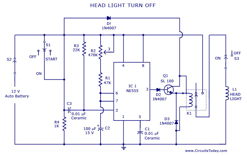
A circuit that can automatically turn off the headlights or lamps of a vehicle after a preset time. This light switching circuit is constructed using a 555 timer integrated circuit (IC). The described circuit utilizes the 555 timer IC in...
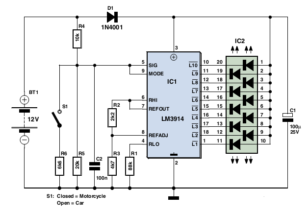
This circuit employs the widely used and easily accessible LM3914 integrated circuit (IC). The LM3914 is straightforward to operate, does not require external voltage regulators due to its built-in voltage regulation, and can be powered by a variety of...

A car alarm, in its simplest form, consists of one or more sensors connected to a siren. The most basic alarm features a switch on the driver's door, which is wired to trigger the siren when the door is...