
Digital Circuits
The NI Multisim software serves as a powerful platform for simulating digital circuits, particularly in educational settings. The four-bit counter design utilizes a 555 timer IC to generate a clock signal, which is essential for synchronous counting operations. This configuration allows students to observe the fundamental principles of digital counting, including binary counting sequences and the behavior of flip-flops.
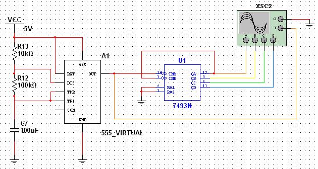
In a typical setup, the 555 timer is configured in astable mode to produce a continuous square wave output, which serves as the clock input for the 7493N four-bit counter. The counter is capable of counting from 0 to 15 in binary, corresponding to the decimal values. The outputs of the counter can be monitored using the oscilloscope, allowing for real-time visualization of the counting process.
The oscilloscope channels are connected to specific output pins of the counter, enabling the observation of the binary states as the counter increments. Each channel can be color-coded for clarity, facilitating easier interpretation of the output states. The integration of ground and trigger connections is crucial for accurate measurements and synchronization of the oscilloscope with the counter's clock signal.
This structured approach not only aids in understanding the operation of digital counters but also familiarizes students with the Multisim interface, enhancing their ability to simulate and analyze electronic circuits effectively. The tutorial's step-by-step instructions ensure that users can replicate the circuit design, fostering hands-on learning experiences.
Furthermore, the potential extension of this project to include an eight-bit decimal counter with seven-segment displays presents an opportunity for advanced exploration. This would involve additional components and a more complex configuration, allowing students to apply their knowledge in a practical context and deepen their understanding of digital electronics.This tutorial explores a common digital concept using the NI Multisim software environment. It examines a four-bit counter that uses a 555 timer IC to generate the clock signal. This tutorial takes less than 30 minutes to complete and consists of 37 steps to show you how to capture and simulate in Multisim. Multisim is an intuitive schematic captu re and SPICE simulation environment for circuit teaching. With specific features designed for the educator to foster learning and guide student exploration of circuit concepts, you can offer your students an interactive environment to visualize circuit behavior with powerful simulation and analysis while abstracting the complexity of SPICE syntax. The component browser organizes the database components into three logical levels. The Master Database contains all shipping components in a read-only format. The Corporate Database is where to save custom components to be shared with colleagues (via a network collection and so on).
Finally, the User Database is where custom components are saved that can be used only by the specific designer. The components (or parts) are organized into Groups and Families to intuitively and logically group common parts together and make searching easier and more effective.
To invoke simulation, you need a power source and a ground somewhere in your circuit to correctly reference voltages and currents in your circuit simulation. If you need multiple components, you can repeat the placement steps as shown or place one component and use copy
By default, the component selection box keeps returning as a pop-up until you have completed placing your components. Close the window to return to the schematic entry window (Close button). You can change this in the global preferences dialog box. You can rotate a part before placement by using the
Once rotated, place the component. Multisim is a modeless wiring environment. This means that Multisim determines the functionality of the mouse tool by the position of the mouse. You do not have to return to the menu to choose between placement, wiring, and editing tools. Complete the wire by moving the mouse to another terminal or just double-click to anchor the termination point of the wire to a floating location somewhere in the schematic window.
You are now ready to run an interactive Multisim simulation; however, you need a way to visualize the data. Multisim provides simulation-driven instruments such as oscilloscopes, wattmeters, and more to help you visualize the simulated measurements.
Select the four-channel oscilloscope instrument from the menu (fifth icon from the left) and place it onto the schematic as you would any other Multisim component. Wire the Channel A, Channel B, Channel C, and Channel D terminals of the oscilloscope to pins 12, 9, 8, and 11 of the 7493N four-bit counter (as shown in Figure 9).
Repeat steps 30-32 to change the color of the segments for the different channels of the oscilloscope. This is important because this determines the color of the signal displayed on the instrument. Also place a Ground at this point to the oscilloscope and provide a trigger by connecting the Trigger pin (labeled T) to the clock signal from the 555_VIRTUALtimer.
Double-click on the oscilloscope on the schematic. You can now visualize the simulation measurements in the oscilloscope interface (Figure 11). Click on the Reverse button of the oscilloscope to change the background color from black to white. Now that you have explored how a four-bit digital counter works, are you able to design an eight-bit decimal counter with two seven-segment displays using a 555 timer IC to generate the clock signal 🔗 External reference
Related Circuits
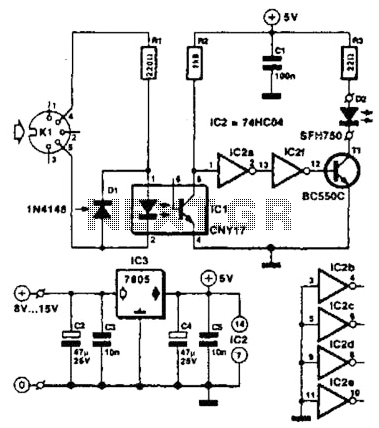
Used for digital control of musical instruments, this transmitter converts digital data signals into equivalent optical signals for a fiber optic cable interface. Optocoupler IC1 provides isolation, driving IC2-a and -b, and T1, ultimately providing a cable driver LED...

The circuit employs a field-effect transistor (FET) at the input of a Schmitt trigger, allowing the use of a low-value capacitor. The trigger, controlled by Q1 and O2, exhibits a hysteresis of approximately 3V, regulated by a 3V zener...
This circuit provides a visual 9 second delay using a 7 segment digital readout LED. When the switch is closed, the CD4010 up/down counter is preset to 9 and the 555 timer is disabled with the output held high....
This document describes the function of a digital stopwatch that counts from 0 to 99 seconds. The stopwatch utilizes four integrated circuits from National Semiconductor, although alternative components could achieve similar results. The circuit diagram is presented in an...
The 1N4001 is a 1 Amp silicon rectifier with a voltage range of 50 to 1000 volts. It features guaranteed high-temperature soldering, high current capability, a diffused junction, low reverse leakage, and utilizes a void-free molded plastic technique for...
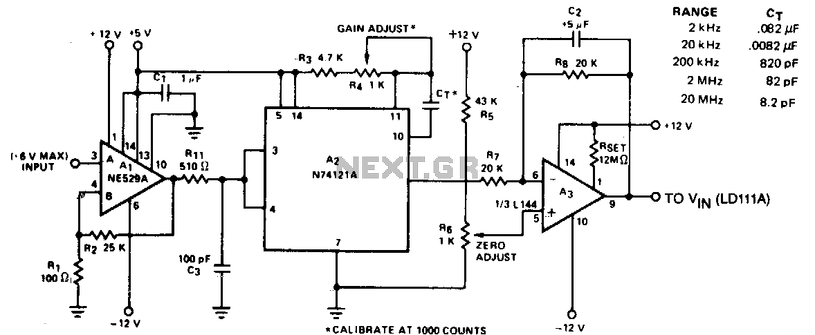
The circuit converts frequency to voltage by taking the average DC value of the pulses from the 74121 monostable multivibrator. The one-shot is triggered by the positive-going AC signal at the input of the 529 comparator. The amplifier functions...