
Digital Stopwatch 0-99sec
The digital stopwatch circuit is designed to accurately count seconds and display the result on two 7-segment displays. The first display represents the units of seconds (0-9), while the second display represents the tens of seconds (0-9). The primary components involved in this design include the CD4060 and CD4040 integrated circuits, which are responsible for frequency division and pulse generation. The crystal oscillator provides a stable frequency source, which is essential for precise timing.
In detail, the CD4060 serves as a frequency divider, taking the high-frequency input from the crystal and reducing it through a series of binary divisions. By connecting the output Q14 of the CD4060 to the CD4040, a further division is achieved, resulting in a 1 Hz output. This output pulse is crucial as it serves as the timing signal for the BCD counter, which counts the seconds. The MC14518 BCD counter is configured to increment its count on each 1 Hz pulse, effectively counting each second.
The design also incorporates a visual feedback mechanism through the use of an LED. This LED illuminates with each pulse, providing a clear indication of the counting process. The choice of using a BCD counter allows for efficient counting and display management, where the unit display increments every second, while the decade display increments every 10 seconds. The logic implemented ensures that the displays reset appropriately, maintaining a seamless counting experience.
Overall, this digital stopwatch design exemplifies a straightforward yet effective approach to time measurement using integrated circuits, demonstrating the principles of frequency division, counting, and digital display interfacing in electronic circuit design.We will describe the function of a digital stopwatch, 0 G 99 sec. The function of the stopwatch, relies in the use of 4 integrated circuits, which in this case belong to National Semiconductor ( It is obvious that other integrated circuits can be used to achieve the same result, however in this case we have used the following parts: The circuit that has been used is shown in picture 1. Through the experimental part we will explain each of the parts function, but in order to have a notion of the basic idea, let just say, that this circuit besides the 5V power supply, is fed with a pulse which comes from a crystal. The crystalG ™s pulse is devided properly in order to obtain the 1 Hz pulse which we need in order for the circuit to work properly, and display the seconds on the 7 segment displays, through a procedure which we will explain through the experimental part.
We will begin the description of the digital circuit above. For our convenience we will devide the circuit to 2 parts: the generator, which produces the pulse of the desired frequency, and the part that does the actual counting. The generator of the circuit comprises of the integrated circuits CD4040CM and CD4060CM. We use a crystal which oscillates at a frequency of 4, 194, 304MHz. It is obvious that this frequency is completely useless, as it is too big to be used as it is to our circuit.
What we should is devide this frequency, in a way that in its final form, the pulse will have a frequency of 1Hz, which is the desirable frequency. Initially we use the integrated CD4060, which devides the imported frequency in its input, by forces of 2.
As we can see on the integrated circuit the outputs are marked as Q4, Q5, G Qn. By importing a pulse in the CLK input of the 4060, with a frequency f Hz, we take out of output Qn, a signal which has a frequency equal to f/2n, . So, by exporting the signal out of Q14, knowing that the imported signal has a frequency of 4, 194, 304Hz, we take a signal, which has a frequency of 256Hz.
By importing this signal, to 4040 and by exporting the signal through Q8 we have finally taken an inverted signal, at the frequency of 1Hz. The fact that the signal is inverted, firstly doesnG ™t affect the proper function of our circuit and secondly is due to the inversion of the CLK input as we can see.
This inversion just causes, the following circuit to be triggered with a logical G 0G . By putting a LED on the same output, we have a visual of the counting, as in each positive pulse the diode polarizes positively, and a current passes through it. The signal of 1Hz, which we have taken from the generator, is imported to a BCD counter MC14518. This integrated circuit adds a logical G 1G at each pulse, on its output. του. . The MC14518 is virtually divided into two segment. One counts the units of the seconds, while the other the decades. As we can see in picture 1, the generators pulse is imported to the part which counts the units. This is very logical, as we want in each secont the number of the display to be raised by 1. On the other hand, we want the first display to raise by 1, every 10 seconds. This is why, we ground the CLK input, and we use the signal of Q3 to the CKE input. By using this means, we make sure that the first display will be triggered, only when we have a decreasing signal on Q3; that is, only when the signal drops from logical G 1G to logical G 0G .
As we can see, the first display increments every 10 seconds, which means that after 9 on the second display (1001 on the output of the BCD counter) the first display must be set to zero, while the first must be set to +1. That is that from 1001 Gƒ 0000, and we have a descending pulse, as the last digit descends from logical G 1G to logical G 0G and triggers the BCD counter of the decades.
When the decades display becomes 9 then the circuit goes to the next state, which 🔗 External reference
Related Circuits
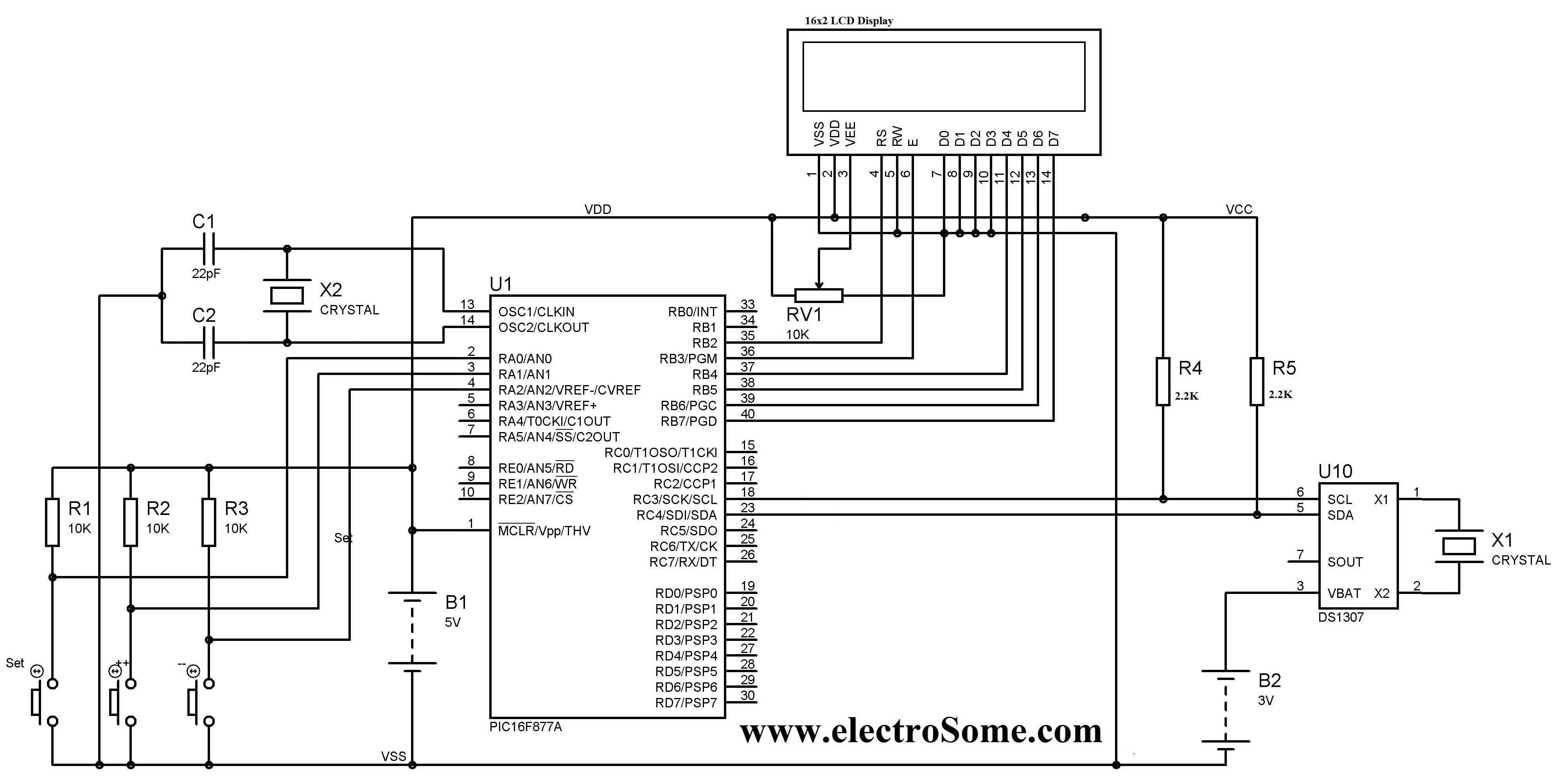
A digital clock can be constructed using a PIC microcontroller, DS1307 real-time clock (RTC), and a 16x2 LCD display. The DS1307 RTC operates in either 24-hour or 12-hour mode with an AM/PM indicator. It adjusts automatically for months with...
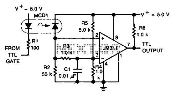
An optoelectronics device is utilized to couple a digital (TTL) signal to another system. The photodiode within the optocoupler drives an LM311 configured to generate a TTL-compatible output. This configuration is particularly beneficial in scenarios where grounds cannot be...
The schematic diagram depicted in Figure 1 is designed to synthesize a sinusoidal waveform with a frequency range of 0.01 Hz to 1 MHz. A clock signal is supplied to the input of the binary counter IC1, with a...
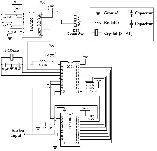
Data Collection - Analog to Digital Conversion and Communicating with a PC through the Serial Port Microcontroller Advanced Kit. The system described involves the process of data collection through analog-to-digital conversion, enabling communication with a personal computer via a serial...
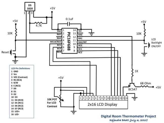
Room temperature plays a vital role in determining human thermal comfort. This digital thermometer is designed to measure room temperature and display it on a LCD screen in both Celsius and Fahrenheit scales. A PIC16F688 microchip is used as...

An FM and AM transmitter integrated into a compact device utilizing the CD4001 integrated circuit. It broadcasts at 20 MHz for AM and 100 MHz for FM. The described transmitter combines both Frequency Modulation (FM) and Amplitude Modulation (AM) capabilities...