
Digital Clock Circuit-CMOS 4047
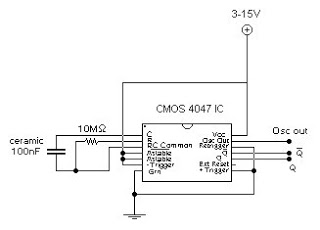
The circuit design utilizes the CMOS 4047, which is a versatile device capable of operating in both monostable and astable modes. In astable mode, the 4047 produces a continuous square wave output, the frequency and duty cycle of which can be adjusted through external resistors and capacitors connected to its timing pins. This square wave output is characterized by its clean transitions and low power consumption, making it suitable for driving digital logic circuits.
In the context of driving 4-bit binary counters, the square wave output from the 4047 can be connected to the clock input of a CMOS decade counter, such as the 4017 or 4026 series. This configuration allows for counting sequences in binary, where each pulse from the 4047 increments the counter by one. The output of the counter can then be used to drive LEDs or other display devices, providing a visual representation of the counting process.
The circuit can be further enhanced by incorporating additional components, such as diodes for signal conditioning or transistors for buffering the output if higher current drive capabilities are required. Proper power supply decoupling should also be considered to ensure stable operation of the CMOS devices involved. Overall, the combination of the CMOS 4047 and a 4-bit binary counter creates a robust and efficient digital counting circuit suitable for various applications in digital electronics.This circuit provides a digital square wave that can be viewed directly or used to drive other circuits. It used the CMOS 4047 Low-Power Monostable/Astable Multivibrator. As used in Tom Duncan`s Adventures with Digital Electronic`s Book, to drive CMOS Decade of 4-bit binary counters.
🔗 External reference
Related Circuits
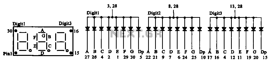
The document presents two types of digital display circuits. The first type (a) utilizes a common anode circuit configuration, while the second type (b) employs a common cathode circuit structure. The common anode display circuit configuration consists of multiple light-emitting...
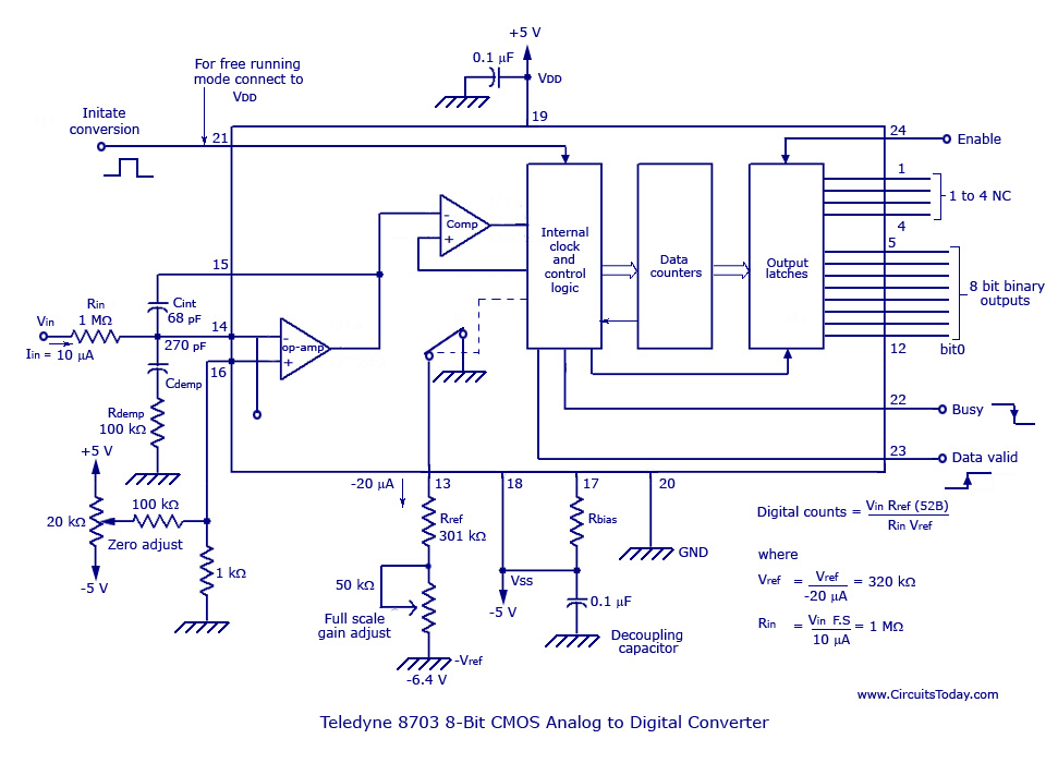
The basic analog to digital (A/D) converter circuit has been previously explained. In addition to this, various types of monolithic analog to digital converters exist, including the integrating A/D, integrating A/D with three-stage outputs, and the tracking A/D with...
The MM5314 is a monolithic MOS integrated circuit that incorporates P-channel low threshold enhancement mode and ion implanted depletion mode devices. It features an internal multiplex oscillator, fast and slow set controls, a single power supply, 7-segment outputs, leading...
This circuit employs switched emitter followers instead of conventional analog switch CMOS chips, resulting in a more effective reduction of crosstalk between channels. It can manage up to 4 Vms with less than -80 dB crosstalk. The circuit design utilizes...
Analog-to-digital converters (ADCs), printed-circuit board (PCB), microcontroller or digital signal processor (DSP), total-harmonic-distortion (THD), signal-to-noise ratio (SNR). Analog-to-digital converters (ADCs) are essential components in modern electronic systems, enabling the conversion of analog signals into digital form for processing by microcontrollers...
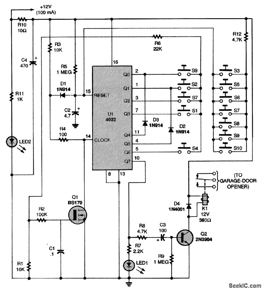
This circuit relies on the input of a correct sequence code. An incorrect number that is not part of the code triggers a reset of the circuit. When the correct code is entered, Q2 activates relay K1 for a...