
Digital display circuit configuration
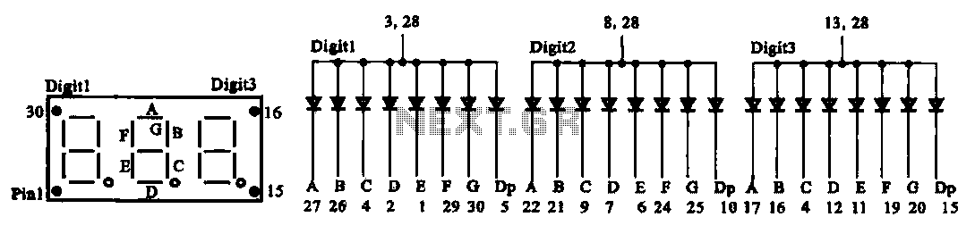
The common anode display circuit configuration consists of multiple light-emitting diodes (LEDs) connected in such a way that the anodes of all LEDs are connected to a positive voltage source. Each cathode is then connected to a control signal that determines whether the LED is turned on or off. This arrangement allows for a simplified control mechanism, as the common positive voltage can be maintained while individual LEDs are activated by grounding their respective cathodes.
In contrast, the common cathode display circuit configuration connects the cathodes of the LEDs to the ground, while the anodes are connected to a control signal that provides the positive voltage. In this setup, activating an LED requires applying a high signal to its anode, allowing current to flow from the anode to the cathode.
When designing these circuits, it is essential to consider the required current limiting resistors for each LED to prevent excessive current flow that could damage the components. The choice between a common anode and a common cathode configuration often depends on the specific application, the type of microcontroller or driving circuit used, and the desired control logic.
Both configurations can be effectively utilized in various applications, including seven-segment displays, alphanumeric displays, and other digital output devices, providing flexibility in design and implementation based on the project requirements.3 shows two kinds of digital display circuit, Total (a) adopt common anode circuit configuration, FIG. (B) the use of common cathode path structure.
Related Circuits

Discharge time relay circuit. The timer utilizes a field effect transistor, providing high timing accuracy and extended timing capabilities. With R3 set to 1,000,000 ohms and C at 200 microfarads, a delay time of 8 hours can be achieved....
This circuit activates an alarm when its sensor comes into contact with water. It employs a 555 astable multivibrator that generates a tone of approximately 1 kHz upon water detection. The circuit consists of a 555 timer configured in astable...
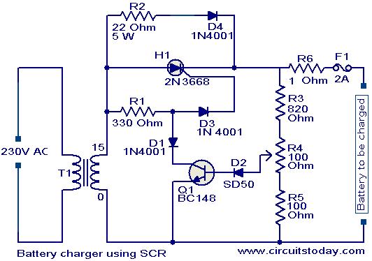
A simple battery charger based on SCR is presented. The SCR rectifies the AC mains voltage to charge the battery. When the battery connected to the charger is discharged, the battery voltage decreases, inhibiting the forward bias voltage from...
A DC-to-DC step-up converter is typically implemented using a transformer, which converts DC voltage to AC voltage, steps it up with the transformer, and then rectifies and filters the output to achieve a higher DC voltage. However, a voltage...
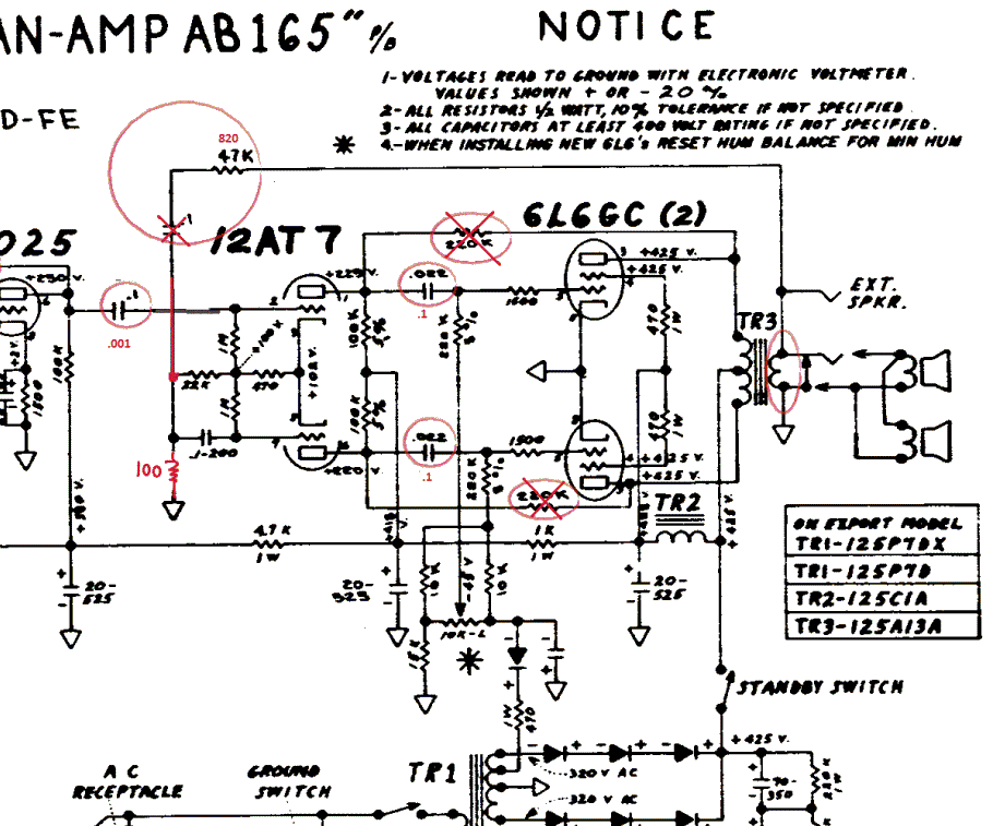
The Fender Bassman is a legendary guitar amplifier recognized by both guitar and bass players. Introduced in 1951, it was primarily aimed at bass guitar players and marketed as a bass amplifier for the Fender Precision Bass guitar, the...

These circuits could be used as the basis for Model Railroad DCC Boosters or PWM motor controllers. The first schematic is for a basic 3 Amp - DCC Booster using the LMD 18200 CMOS, H-Bridge. Included in the design...