
MM5314N Driven Digital Clock Circuit

The MM5314 integrated circuit is designed for use in digital clocks, providing a compact and efficient solution for timekeeping applications. The integration of P-channel MOS technology allows for low power consumption and high reliability, essential for consumer electronics. The internal multiplex oscillator enables the driving of multiple displays without the need for complex additional circuitry, simplifying the overall design.
The common anode configuration of the 7-segment displays not only reduces wiring complexity but also enhances the circuit's robustness by allowing all positive terminals to be connected together, which is particularly beneficial in minimizing the risk of short circuits. The use of transistors to drive the individual segments of the displays ensures that each segment can be controlled independently, allowing for precise representation of time.
The timing accuracy of the circuit is crucial for maintaining correct time, which is why the inclusion of a crystal oscillator is recommended. This oscillator provides a stable frequency reference that significantly enhances the precision of the clock. The design also incorporates various protective measures, such as the use of diodes and resistors, to safeguard the integrated circuit from voltage spikes and excessive current, ensuring longevity and reliability in operation.
The user interface, facilitated by switches S1, S2, and S3, allows for easy adjustments of the clock settings, accommodating user preferences for 12-hour or 24-hour formats and enabling quick corrections to the time. The push-to-make functionality of the switches ensures that adjustments can be made efficiently without the need for continuous engagement, enhancing user experience.
In summary, the MM5314-based digital clock circuit represents a well-engineered solution for timekeeping, combining advanced MOS technology with practical design considerations to deliver accurate and reliable performance in a user-friendly package.MM5314 a monolithic MOS integrated circuit that utilizes P-channel low threshold, enhancement mode and ion planted, depletion mode devices which has features such as internal multiplex oscillator, fast and slow set controls, single power supply, 7-segment outputs, leading zero blanking, operating at 50 Hz or 60 Hz, and 12 or 24 hour display fo rmat 7 Segment LED is a form of electronic display device for displaying decimal numerals that is an alternative to the more complex dot-matrix displays also known as seven-segment indicator A digital clock is a type of clock in which the time is displayed in a numerical form being associated with electronic devices. It uses a digital display rather than moving hands. The basis of the circuit design evolves in a single MOS IC MM5314N. Other necessary circuits are operated through the MM5314 IC which works together with six common anode 7-segment displays.
The multisegment LED common anode configuration reduces the number of wires between the LED modules where all positive ends are connected together. In practical design, the longest pin of the LED is the positive or the anode part. The 7-segment displays are driven by thirteen transistors consisting of BC550 and BC560. The timing of the circuit is determined by the frequency of the network with a value of 50 Hz, which imposes the simplest solution.
To maintain a stable output frequency, a crystal oscillator may be used. It uses a quartz crystal to produce fixed frequency oscillations where accuracy and stability are the primary considerations. It uses the mechanical resonance of a vibrating crystal to produce a very precise frequency from the creation of an electrical signal.
The six displays of 7-segment common anode provide the output for the time. LEDs DS1 and DS2 represent the Hour, LEDs DS3 and DS4 represent the Minutes, and LEDs DS5 and DS6 represent the Seconds. The collector of transistors Q8 to Q13 powers the common anode of each display. Each display consists of individual LEDs a, b, c, d, e, f, & g, are linked in parallel combination, which are then driven by the transistors Q1 to Q7.
This type of connection creates a multiplexing system with a frequency of 1 KHz that is controlled by the RC circuit R3 and C3. The power supply contains the typical circuit having a bridge rectifier across the secondary coil with a parallel capacitor across the bridge.
The resistor R2 and capacitors C2 to C5 handles the separation and limiting of voltage to protect the integrated circuit from surge and peak voltages. The rectified vibrations in pin 16 are limited by the diode D1 while resistors R18 to R24 are limiting the excess current from the LED.
The use of switch S1, if put in position 1, is to adjust the clock to the required time and display. It will remain open unless it is switched to the other position which causes the display to be in a fixed value and save the settings, resuming the operation of the clock. In this scenario, the clock may be placed with a tolerable distance to avoid the effect of light from the LED display.
Switch S2 on the other hand is responsible for adjusting the clock to operate on a 12-hour or 24-hour basis by changing the positions of the contacts. The adjustments of seconds are made possible when switch S3 is in position 1. The setting for the seconds is saved when the contact is changed to position 2. During an interruption in the operation of the clock, switches S3, S4, and S5 can be used for alterations.
These are push-to-make switches which return to its normally open or OFF position upon releasing the button, like the standard doorbell switch. The frequency of the main voltage around 50 Hz or 60 Hz is fed into pin 11 which is connected to pin 2 if the main voltage is 110 VAC at 60 Hz.
Otherwise, pin 11 will not be connected anywhere if the main voltage is 220 VAC at 50 Hz. Pin 16 handles the incoming 50 Hz or 60 Hz at the input with the sample from the main voltage. The counter circuits are triggered by the sample function which becomes the adjustment of time. Having 110 V causes the pin 11 to connect Vss at pin 2 while having a 220 V nulls the function of pin 11. 🔗 External reference
Related Circuits
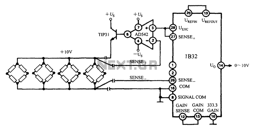
The 1B32 application circuit features multiple pressure sensors as illustrated in the figure. Excitation power is supplied through the AD542, which is followed by a TIP32 transistor that drives multiple bridge sensors. The AD542 operates as a Bi-FET in...

This sensor switch circuit features nine channels and consists of three integrated circuits along with several resistors. The 74HC147, which has a high input impedance, enables the use of 4.7 MΩ resistors to establish a logic level "high" for...
The heating element is connected in series with two back-to-back 16 amp silicon-controlled rectifiers (SCRs), which are controlled by a small pulse transformer. This pulse transformer features three identical windings; two of these windings provide trigger pulses to the...
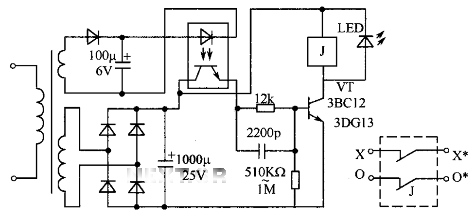
The circuit protection mechanism utilizes optocouplers for on-off control. Under normal voltage conditions, the output from the optocouplers is minimal, and the VT transistor operates in reverse bias. However, if the circuit voltage increases due to reasons such as...
Incorporate resistors in a parallel configuration to enhance audio input. To control the volume for each input channel, integrate a linear trimmer or potentiometer with the following configuration: pin 1 connects to ground, pin 2 serves as the output,...

This is a design of the circuit diagram for an RS422 interface. Connector K1 is connected to the serial port of the PC, and power for the PC side of the circuit is obtained from the signal lines DTR...