
Digital Combination Lock
The described circuit utilizes the CMOS 4017 decade counter, which is designed to count from 0 to 9 in response to clock pulses generated by the pressing of pushbutton switches (PBS). Each pushbutton corresponds to a specific input in the sequence, and the circuit is structured to require a predefined number of presses for each button to activate the subsequent button.
The debouncing of the pushbuttons is accomplished using two gates from a CMOS 4001 quad 2-input NOR gate. This configuration effectively removes any noise or unintended bounces that may occur when a button is pressed, ensuring that only a clean pulse is sent to the input of the CMOS 4017 counter. The output of the counter is then routed through an AND gate to control the activation of the next stage in the sequence.
For example, PBS A must be pressed a specific number of times to enable PBS B. The same principle applies to PBS C and PBS D, creating a sequence that requires users to input a precise code to progress through the circuit. Specifically, for the fourth counter (IC4), PBS D must be pressed seven times to achieve the desired output.
This design effectively demonstrates a simple yet efficient method of creating a multi-step input sequence using CMOS technology, ensuring reliable operation through the use of debouncing techniques. The combination of the CMOS 4017 and the NOR gates provides flexibility and reliability in applications where precise input sequences are necessary.The circuit above above makes use of the CMOS 4017 decade counter IC. Each depression of a switch steps the output through 0 - 9. By coupling the output via an AND gate to the next IC, a predefined code has to be input to create the output. Each PBS switch is debounced by two gates of a CMOS4001 quad 2-input NOR gate. This ensures a clean pulse to the input of each CMOS 4017 counter. Only when the correct number of presses at PBS A will allow PBS B to become active. This is similar for PBS C and PBS D. At IC4, PBS D must be pressed 7 times. 🔗 External reference
Related Circuits
A mechanism allows a standard potentiometer to function as a digitized potentiometer, converting each setting into a number between 0 and 15. This information is utilized to determine the duration for each step. An analog-to-digital converter (ADC) is designed...
To initiate the process, the LOAD switch and Reset switch must be pressed simultaneously within 24 seconds; otherwise, the countdown will commence from 99. A pulse input can be connected to a 555 astable multivibrator, but it must be...

The latest circuit diagram of the AD2496 is presented here. All modifications intended and described in the article regarding the prototype have been implemented. Additionally, two current-compensated chokes have been introduced to enhance electromagnetic compatibility (EMC) immunity. While these...
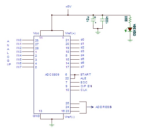
Analog to digital converter modules are utilized in microcontroller-based projects where analog signals need to be transformed into digital signals for further processing in a microcontroller. The integrated chip employed for this purpose is the ADC 0809. This post...
A Super GameBoy was acquired, but it has been observed that the sound pitch is significantly higher than that of an original GameBoy. This discrepancy arises due to a mismatch in CPU clock frequencies: 4.194304 MHz for the original...
After the SCL line is high, the SDA line must be held low to indicate that the data being transmitted is legally binding. The data can only change when the SCL line is low. During the transfer of a...