
24 Second Shot Clock Circuit
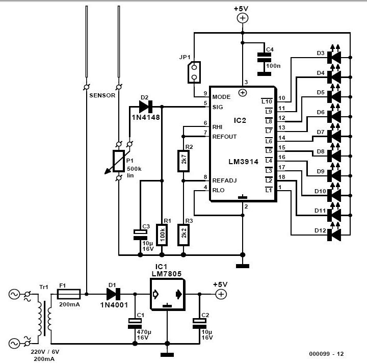
The described circuit operates as a countdown timer with specific functionalities tied to user inputs and component interactions. The initial setup requires the simultaneous pressing of the LOAD and Reset switches within a defined time frame. This condition is essential to prevent the timer from defaulting to a countdown from 99.
The integration of a 555 timer configured as an astable multivibrator allows for the generation of pulse signals, which can be calibrated for accurate timing. This calibration is crucial for ensuring that the timer reflects real-time accurately. The PAUSE switch is equipped with a debouncer circuit, which is necessary to prevent false triggering due to mechanical bouncing when the switch is pressed or released. This debouncing ensures the counter maintains its integrity during pause and resume operations.
Upon reaching a count of 00, a NOR gate is employed to provide a logic high output, which serves as a trigger for two transistors. These transistors act as switches that control the buzzer and light, signaling the end of the countdown. The output from the NOR gate effectively ensures that both transistors are activated simultaneously, providing a clear and audible indication of the countdown completion.
The design incorporates a power supply of +5V, which is sufficient for powering the 555 timer, NOR gate, transistors, and other associated components. The overall circuit design emphasizes reliability and user interaction, ensuring that the countdown timer functions as intended while providing feedback through visual and auditory signals. The use of transistors allows for efficient control of higher power devices such as buzzers and lights, ensuring that the circuit can be utilized in various applications requiring countdown functionalities.To start in 24 seconds; 24s LOAD SW and Reset SW should be push simultaneously. If not, the count will start in 99. Pulse input can be connected to 555 astable multivibrator but must be calibrated for real time clock. The PAUSE SW must have a Switch Debouncer so that the counter will count normal when counting is paused and then turn-on.
When the count reach 00, the NOR gate will have an output of logic1 that will turn on the two transistor. The buzzer will rung and light will turn on. The two transistors are continuously turn-on not until LOAD SW and Reset SW is push. All have a +5v power supply. 🔗 External reference
Related Circuits
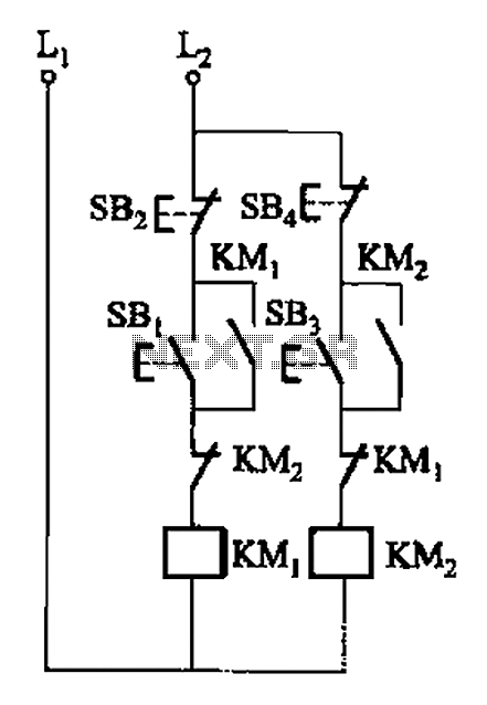
A, B, and two electric motors allow simultaneous operation through interlock control. The two motors can be connected in series with each other using normally closed contacts in the respective coil circuit. The circuit design facilitates the interlocking operation of...
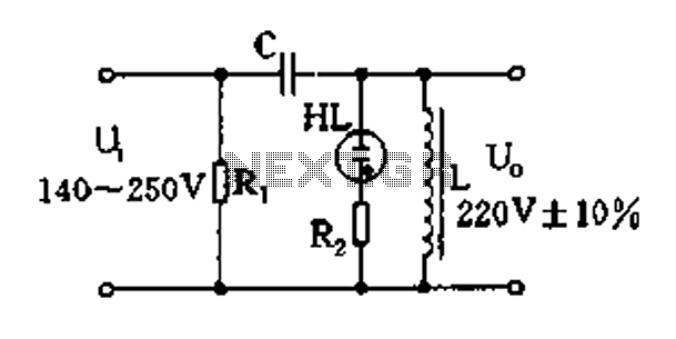
Easy exchange of magnetic saturation voltage regulator circuit The magnetic saturation voltage regulator circuit is designed to stabilize output voltage levels by utilizing magnetic saturation principles. This circuit typically employs a magnetic core, which operates in saturation to regulate...
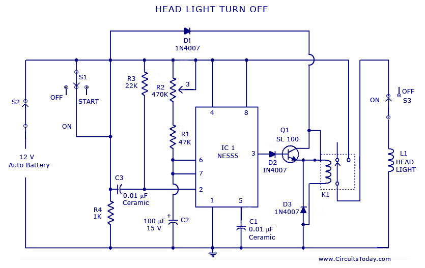
A circuit that can automatically turn off the headlights or lamps of a vehicle after a preset time. This light switching circuit is constructed using a 555 timer integrated circuit (IC). The described circuit utilizes the 555 timer IC in...
For individuals who prefer not to engage directly with soil, this simple soil moisture tester efficiently assesses the condition of their plants and the level of care they require. The soil moisture tester is a device designed to measure the...
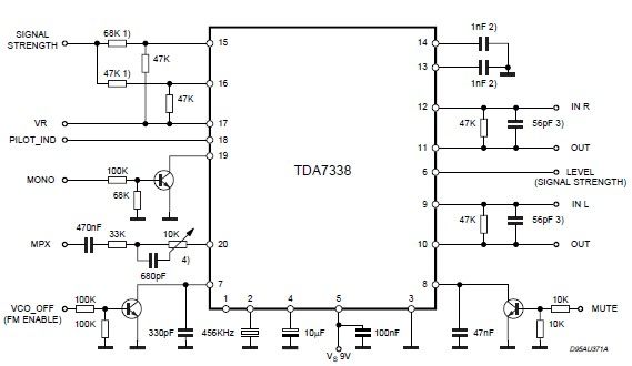
The pilot detector output is configured as an open collector output, necessitating the use of an external pull-up resistor. To set the decoder to "MONO," Pin 19 must be clamped to a voltage lower than 0.8V. The open collector output...
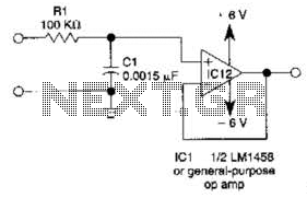
This simple filter utilizes an RC section as the filter element, incorporating a voltage follower to manage other frequencies. The -3 dB point is calculated as 1/(6.28 * RXCV), resulting in a response that drops 6 dB per octave...
Warning: include(partials/cookie-banner.php): Failed to open stream: Permission denied in /var/www/html/nextgr/view-circuit.php on line 713
Warning: include(): Failed opening 'partials/cookie-banner.php' for inclusion (include_path='.:/usr/share/php') in /var/www/html/nextgr/view-circuit.php on line 713