
Digital dice circuit
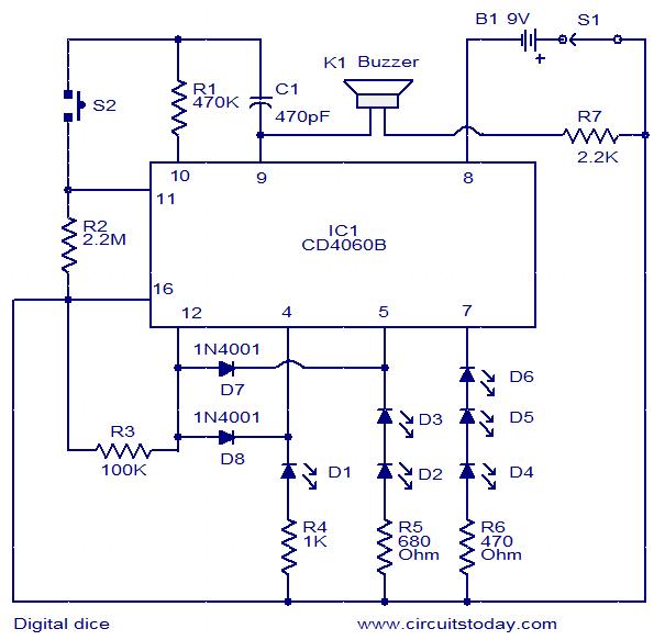
The digital dice circuit is designed around the CD4060B integrated circuit, which combines a binary ripple counter and an oscillator in a single package. The oscillator generates a clock signal at a frequency of 2 kHz, which is used to drive the counter. The counter operates in a binary count sequence, where each clock pulse increments the counter value until it reaches a predefined limit.
In this circuit, the counter outputs are connected to six individual LEDs (D1 to D6), which visually represent the numbers 1 through 6. Initially, when the circuit is powered on, the oscillator is disabled, and the counter outputs remain at logic zero, resulting in all LEDs being illuminated. The user initiates the counting process by pressing the pushbutton switch S2, which enables the oscillator. As the oscillator generates clock pulses, the counter begins to increment its output.
The output states of the counter are monitored at pins 4, 5, and 7 of the CD4060B. The outputs change sequentially from 000 (all LEDs off) to 101 (indicating the number 3 on the dice). The circuit is designed to reset the counter before it can reach the binary state 110 (representing the number 4). This is accomplished through the inclusion of resistors R3 and diodes D7 and D8, which prevent the counter from advancing beyond the 101 state. When the counter attempts to transition to 110, the diodes become reverse biased, sending a high signal to the reset pin (pin 12) of the CD4060B, which resets the counter back to 000.
While the pushbutton switch S2 is held down, the micro buzzer is activated, providing an audible indication that the counting is in progress. Once the button is released, the counting halts, and the last displayed state of the LEDs remains lit, representing the final random number generated by the circuit. This design effectively simulates the randomness of a traditional dice roll, providing both visual and auditory feedback to the user.This is a simple and easy to construct digital dice circuit. The circuit is based on a single IC, CD4060B. The dice consists of six LEDs marked D1 to D6. The number of LEDs glowing indicates the numeral. The heart of this circuit is 14 stage binary ripple counter IC CD4060B. The IC also has a built-in oscillator. The oscillator output (here 2 KHz) is used to clock the binary ripple counter. The counter increments by one in its natural count sequence each time it is clocked. The oscillator in initially inhibited as long as the pushbutton switch S2 is not pressed. The counter outputs will be in logic zero state and all the six LEDs will be ON. As the push button S2 is pressed, oscillator is enabled and the counter starts counting. The counter outputs (pin 4, 5 & 7) changes from 000 to 101 and then resets to 000 to repeat the sequence. After 101 the counter does not advances to 110 because of R3, D7 & D8. When the counter just advances from 101 to 110 the diodes D7 & D8 become reverse biased and makes the reset pin (pin 12) high to reset the counter.
The counter counts as long as the push button switch S2 is pressed. Also the micro buzzer will sound as long as the IC is counting. When the push button switch S2 is released, the counting is stopped and holds the existing state to represent the random number. 🔗 External reference
Related Circuits
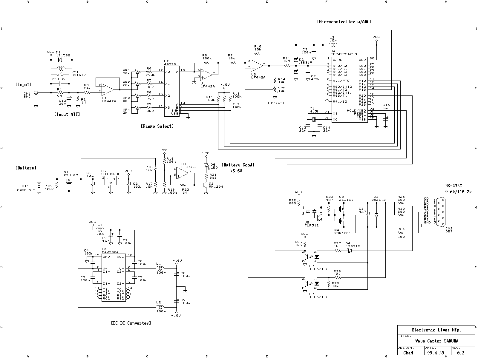
This is a portable oscilloscope adapter that can be held in a breast pocket. Its operation is only sampling and sending to the host PC. Most of the functions of the oscilloscope are processed by the host PC. Therefore,...
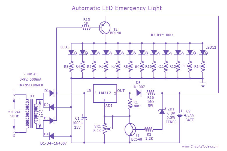
This is a cost-effective and straightforward emergency light circuit developed for CircuitsToday. It is an automatic emergency lamp with daylight sensing capabilities, meaning it detects darkness and turns on automatically, while also sensing daylight to turn off. The circuit...
The drive circuit is a basic drive recently designed to accommodate a 27mm passive piezoelectric buzzer, aiming for a sound output exceeding 100dB while minimizing power consumption. Due to constraints related to product cost and structural size, the circuit...
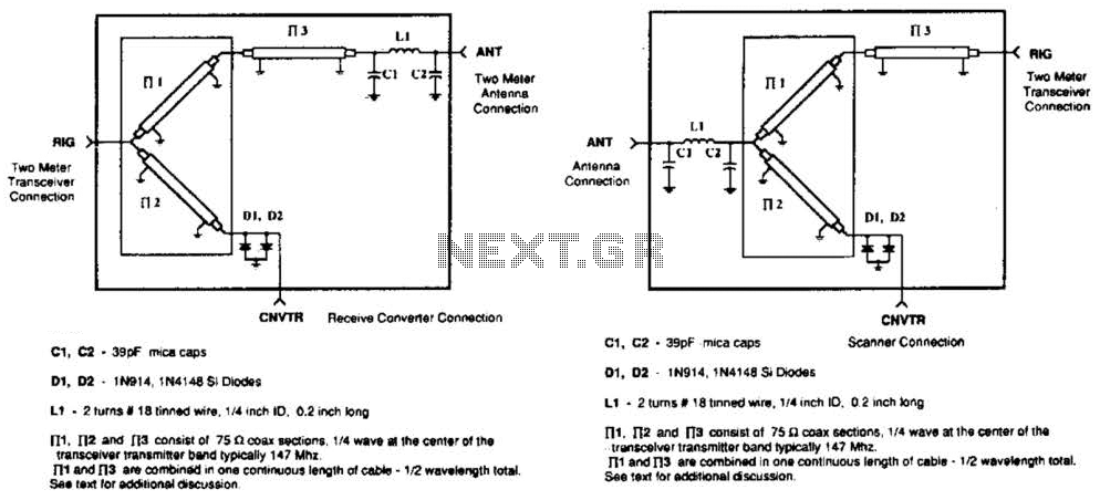
A pair of diodes and a quarter-wave transmission line are utilized as an automatic TR switch. D1 and D2 conduct during transmit periods, short-circuiting the scanner input. In this mode, the quarter-wave line appears as an open circuit. In...
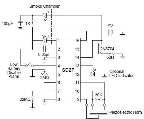
This smoke detector circuit diagram is based on the SD2 CMOS Photo-Electric Smoke Detector Integrated Circuit manufactured by Supertex Inc. It includes almost all the necessary components to build a simple and highly efficient smoke detector project. The LED...
This circuit is designed to detect the approximate percentage of salt in a liquid. After careful calibration, it can provide a quick, rough indication of salt content in liquid foods for dietary purposes. The operational amplifier IC1A is configured...
Warning: include(partials/cookie-banner.php): Failed to open stream: Permission denied in /var/www/html/nextgr/view-circuit.php on line 713
Warning: include(): Failed opening 'partials/cookie-banner.php' for inclusion (include_path='.:/usr/share/php') in /var/www/html/nextgr/view-circuit.php on line 713