
Mini PC Digital Oscilloscope
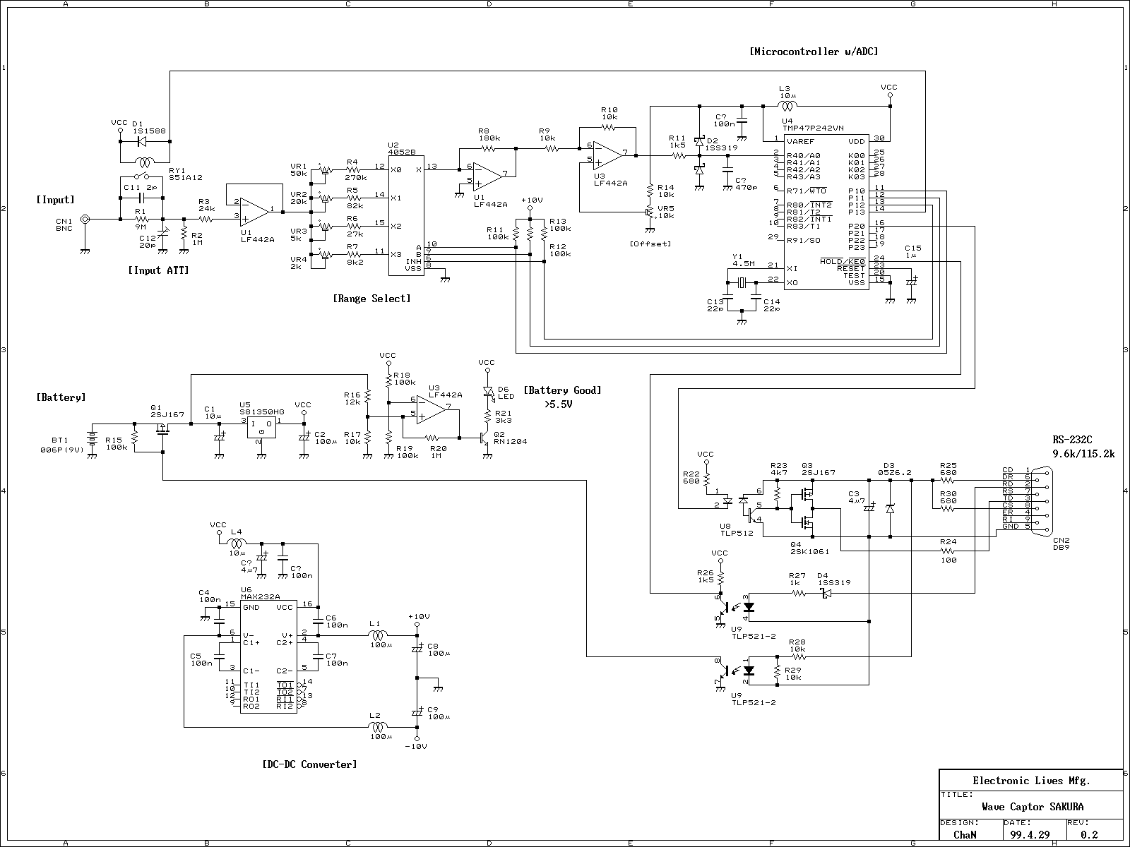
The portable oscilloscope adapter is designed to facilitate the sampling of analog signals and the transmission of this data to a host PC for further processing and visualization. The core component of the adapter is the microcontroller, which handles the acquisition control. The TMP47P242VN microcontroller, while effective, is not readily available, prompting the recommendation to utilize alternative microcontrollers such as the PIC or AVR series, which may offer more accessibility and ease of programming.
The communication between the oscilloscope adapter and the host PC is established through a serial interface adhering to the N81 format, ensuring reliable data transfer at a rate of 115.2 kbps. This high-speed communication is vital for real-time data transmission, particularly when the sampling rate reaches 10 kSa/sec. The RS-232C interface, while a limiting factor for higher sampling rates, suffices for lower frequency applications.
Power management for the analog components is efficiently handled by the MAX232AC, which generates the necessary dual polarity supplies from a single +5V source. This is particularly beneficial when interfacing with operational amplifiers (OPAMPs), enabling them to function optimally across a range of input signals.
The oscilloscope adapter's operation is structured around a command-response protocol. Upon initialization, the microcontroller enters a command waiting state, ready to receive commands from the host PC. The defined range for command values (0x50 to 0x5F) ensures that only valid commands are processed, enhancing the robustness of the system. The system's design also incorporates a delay mechanism to stabilize the output before transitioning into the sampling state, ensuring accurate data acquisition.
In summary, this portable oscilloscope adapter represents a compact solution for signal sampling and analysis, leveraging readily available microcontroller technology and established communication protocols to deliver effective performance in various applications. The emphasis on flexibility in microcontroller selection and the straightforward command structure allows for ease of use and adaptability in different operating environments.This is a portable oscilloscope adapter that it can be held in breast pocket. Its operation is only sampling and sending to host PC. The most of functions of the oscilloscope are processed by host PC. Therefore, oscilloscope adapter can be simplified. This oscilloscope adapter using a TMP47P242VN 4bit microcontroller for acquisition control. But it is difficult to obtain and to programm personaly, so that I recommend to replace the microcontroller with any other microcontroller, such as PIC and AVR, when you want to follow this project. The details of the acquisition controller is as follows. Communication format between host PC and oscilloscope adapter is N81 (no parity, 8 data bits, one stop bit).
Data transfer rate between oscilloscope adapter and host PC is 115.2kbps. For others there is no especialy technique, only amplitude input signal, sampling with microcontroller with integrated ADC, and sending wave form data to host. The sampling rate of 10ksa/sec is dissatisfied as a digital oscilloscple. This restriction on sampling rate is by be linked between acquisition unit and host PC with the RS-232C.
However, it will be useful on the lower frequency signal. Negative and positive powers for the analog circuit is generated with charge pump of the MAX232AC. The MAX232AC is useful when using OPAMP with single +5V power supply. For range changing, this is controlled by host PC with atteneter and amplification value control commands. This is the minimun required transfer rate for real-time transmission of sampled data of 10ksa/sec. And command transfer speed of from host PC to oscilloscope adapter is 9.6kbps. The acquisition controller will enter state of command waiting after power-up. One byte of command value range is from 0x50 to 0x5F, any other value will be ignored. The controller outputs lower four bits to P01-P03, wait for one milisecond, and enter to sampling state (sampling loop).
In sampling state, anything data is raceived from host PC, acquisition controller will return to command waiting state. Host PC must send a 0x00 before sending any command. When above protocol is satisfied, control program will be able to use without any patches. But remaking the controll program as windows based application will better than DOS based application.
🔗 External reference
Related Circuits
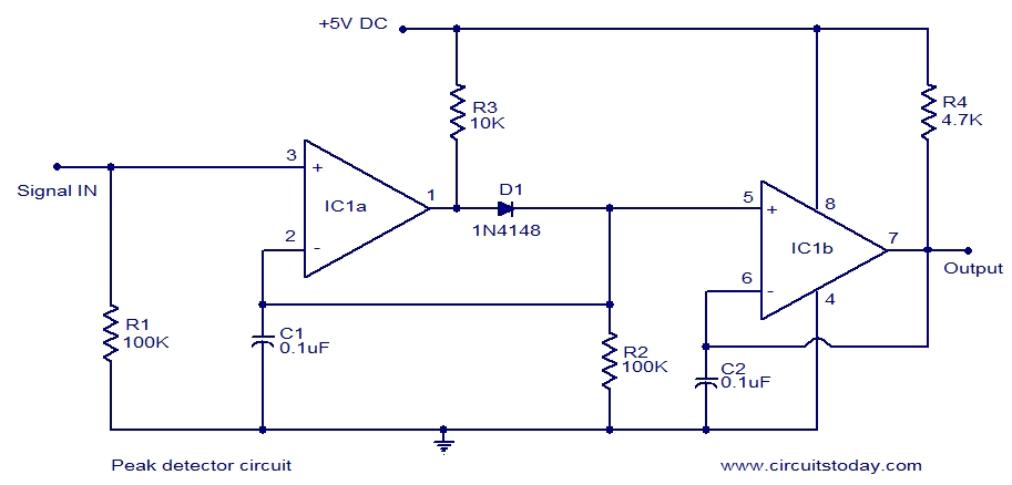
LM339-based peak detector circuit. Simple and easy to construct. Operates from a 5V DC single supply. LM339 is a dual comparator. The LM339-based peak detector circuit is designed to capture and hold the peak value of an input signal. This...
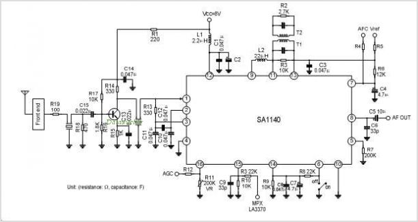
The SA1691 is a monolithic integrated circuit designed for radio cassette tape recorders, clock radios, and headphone radios. This IC includes all functions from the antenna to the audio power amplifier of AM/FM radio, produced by Silan. The SA1691 integrated...
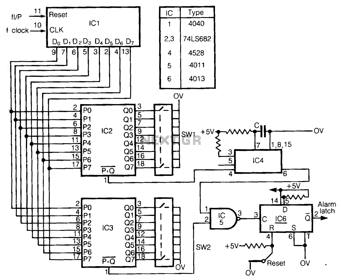
This circuit detects frequency variations that exceed preset limits. IC1 functions as a binary counter connected to the clock frequency (FcLK). The outputs from IC1 are compared with preset values set by IC2 and IC3. The input signal, which...
The input mentions the 89S51/52 microcontrollers, but the accompanying image shows the 89C51. Clarification is needed regarding which microcontroller should be used with the provided .hex file without requiring changes to the file. The 89S51 and 89S52 are part of...
The piezo diaphragm can originate from a music card, and if two or three diaphragms are available, they can be connected in parallel, as illustrated in the diagram, to observe their impact on the output frequency. The only component...
The Clock Controller was designed to be an exemplary of using 'C' language to control timer0 interrupt, 7-segment LED and keypad scanning. It provides 1-bit sink current driving output, for driving a relay, opto-triac, say. Many projects requiring 7-segment...