
Smoke Detector circuit diagram using SD2 IC

The smoke detector circuit utilizes the SD2 CMOS Photo-Electric Smoke Detector IC, which is specifically designed for efficient smoke detection in consumer electronics. This integrated circuit operates by emitting infrared light through an LED, which is modulated by a pre-driver circuit. The external transistor acts as a switch, controlling the power to the IR LED, allowing it to operate at a low duty cycle to conserve energy.
The timing of the IR LED pulses is crucial for the operation of the smoke detector. The external timing resistor sets the pulse period, allowing customization based on the specific requirements of the application. This flexibility is essential for adapting the circuit to different environments or sensitivity levels.
Adjustable sensitivity is achieved through the inclusion of a trimmer resistor, which allows for fine-tuning of the IR LED pulse width. This feature enhances the detector's ability to differentiate between smoke and other environmental factors, thus improving reliability.
The light-sensing component of the circuit is a silicon photovoltaic cell, which converts incident light into an electrical signal. By maintaining the cell at near zero bias, the circuit minimizes leakage currents, ensuring that even low-level signals, as low as 1 mV, can be effectively detected. When smoke is present, the amount of light reaching the photovoltaic cell decreases, triggering an increase in the pulse repetition rate of the IR LED, which activates the alarm system.
In terms of power requirements, the circuit is designed for low power consumption, making it suitable for battery-operated applications. A 9 volts DC power supply or a 9 volts battery is necessary to power the circuit, ensuring reliable operation in various settings. This design approach aligns with the growing demand for energy-efficient smoke detection systems in residential and commercial applications.This smoke detector circuit diagram is based on the SD2 CMOS Photo-Electric Smoke Detector Integrated Circuit manufactured by Supertex INC and include almost all needed components to build a very simple and high efficiency smoke detector project. The LED predriver output pulses an ex ternal transistor which in turn, switches on the infrared ligh
t emitting diode at a very low duty cycle. The desired IR LED pulse period is determined by the value of the external timing resistor. The Smoke Sensitivity is adjustable through a trimmer resistor which varies the IR LED pulse width. The light sensing element is a silicon photovoltaic cell which is held at near zero bias to minimize leakage currents. The circuit can detect signals as low as 1 mV and generate an alarm. The IR LED pulse repetition rate increases when smoke is detected. Because the SD2 CMOS Photo-Electric Smoke Detector IC is designed for use in low power, battery operated, consumer applications it needs a 9 volts DC power supply (or a 9 volts battery ).
🔗 External reference
Related Circuits
One of the simplest methods to demonstrate the autonomous motion of a robot is by having it follow a line. There are competitions for the fastest robots or those capable of navigating complex line mazes. Lines can be high-contrast...

All the adapted numbers of the cipher are in the aforementioned line. To set the adjustment of the cardinal of the code, we accept to set the acceptable affiliation amid the bulge of the 7414 ascribe and the adapted...
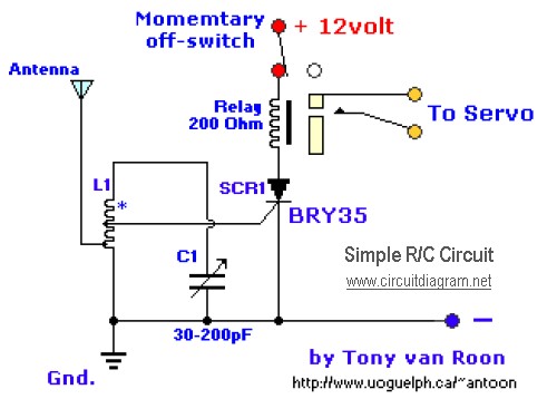
The diagram illustrates a straightforward and efficient receiver designed for activating garage doors, starter motors, alarms, warning systems, and various other applications. The silicon-controlled rectifier (SCR) utilized in this circuit features an exceptionally low trigger current of 30 µA,...

The primary components of this doorbell circuit are two NE555 timer integrated circuits (ICs). When switch S1 is pressed momentarily, the loudspeaker emits a bell tone for the duration determined by the monostable multivibrator configuration around IC1. Pressing switch...
The electric car remote control circuit diagram enables the model car to move forward and backward, as well as turn left and right. It is simple and easy to operate. The radio remote control receiver demodulation circuit utilizes TWH9238...

This document outlines the construction of a simple joule thief circuit. A joule thief is a versatile device, particularly useful for powering LED lights from low-voltage power supplies. It is capable of extracting energy from nearly depleted batteries, making...