
Digital frequency counter
The frequency counter circuit is a sophisticated electronic system designed to accurately measure and display the frequency of incoming signals. The core components of the circuit include the counter ICs, a signal conditioning circuit, and a display interface. The signal conditioning circuit is crucial for converting analog signal waveforms into digital pulses suitable for counting. This typically involves a Schmitt trigger or comparator configuration to ensure that the output is a clean square wave.
The counter ICs, such as the 74HCT190, are connected in a cascading manner to form a multi-digit display. Each IC handles a single digit of the BCD output, and the CMOS technology ensures low power consumption and high-speed operation. The CMOS decoder IC translates the BCD output into a format that can drive seven-segment displays, allowing for clear and immediate visual representation of the counted frequency.
The control circuit orchestrates the timing of the counting operation. It ensures that the counter is activated for a predetermined gating time, during which it counts the incoming pulses. After the counting period, the control circuit triggers the display to update with the new frequency reading, while simultaneously resetting the counter for the next measurement cycle. The precision of the timing signals generated by the control circuit is vital for accurate frequency measurement, making the choice of a stable crystal oscillator essential.
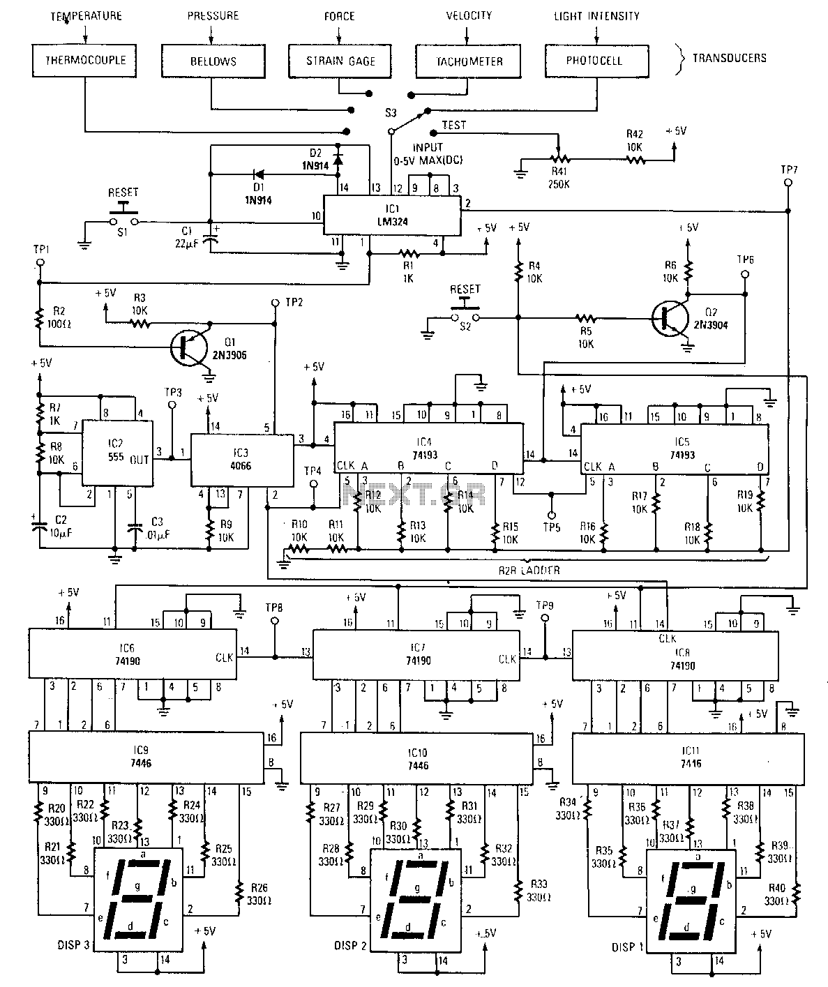
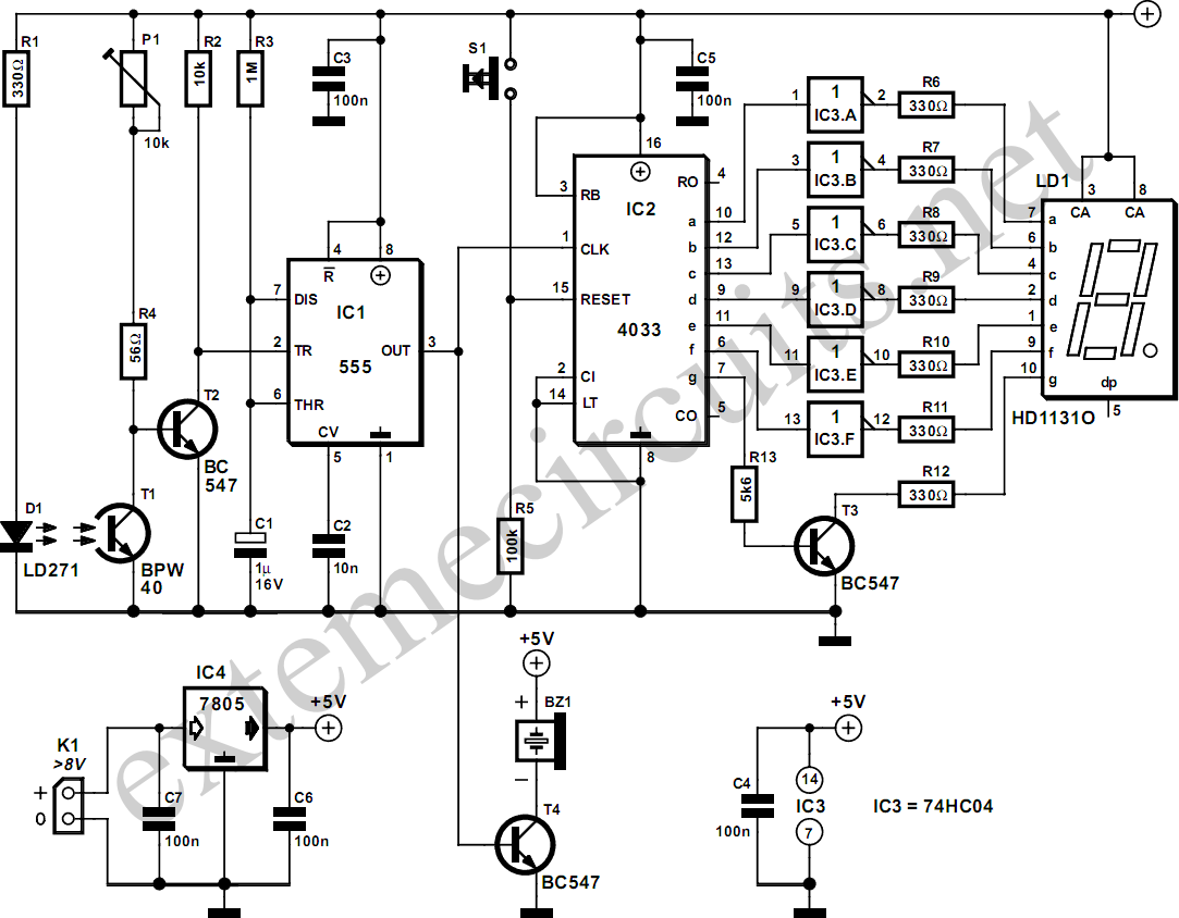
In summary, this frequency counter circuit is capable of measuring a wide range of frequencies with varying resolutions based on the application requirements. Its design allows for flexibility in display digits and ease of use, making it a valuable tool in electronic measurement and diagnostics.The frequency counter has to count the number of cycles per second of an incoming signal. Hence we need a device to count. In electronics circuits, counter ICs are available for counting. These IC`s can count the input pulses. The count is given as coded output from the IC (in binary form or BCD form). The count must be converted into decimal digi t to be understood by human beings. More number of IC`s can be cascaded to increase the number of digits. The number of digits required for the counter to display the count value depends on the application and the accuracy needed. In our design we use a single 4 bit BCD high-speed CMOS counter chips. One chip is used for one digits and we use 7 similar ICs to get seven digit counter. Also we use CMOS decoder IC to decode the BCD out put of the counter to drive 7 segment displays. Since the counter can count only digital pulses, we need to convert the incoming signal wave to digital pulse or we should obtain one pulse for every input wave.
Hence we need a special circuit to shape the input wave into a square wave of same frequency and amplitude confined to the TTL signal levels. A signal conditioning section is needed for this purpose. Besides the above initial stages, some times a few more additional stages such as input protection stages, filter stages, etc are can be found in some designs.
The input whose frequency is to measured is given to the input stage consisting of the above and the out put of this stage is the square pulses. Now the square pulses are given to the counter to count the number of pulses for a fixed duration. If the duration is 1 seconds, then the counter displays a value that equals to the number of cycles per second, now if we want to measure a frequency of say 20MHz, the counter should display 20000000.
this means the counter should have 8 digits to display. Now the resolution of the counter ( minimum change of frequency that can be displayed ) is 1Hz. If we do not require that much of resolution, we can reduce the number of digits. For example, if we are counting the input cycles for a duration of 0. 1 seconds, the display shows 2000000. Now if we put a decimal points after two digits from the left of the display, the frequency can be read in MHz, in both cases, the resolution for the later being 10Hz. The time for which the counter is counting is called as gating time and if the gating is say 1 milli second, we get a display with resolution of 1kHz.
A frequency counter must always count the input frequency and display frequency. This means there should be an arrangement to count the input for a fixed time, display the reading. While displaying the reading, the counter should clear again to read input again. Then only we get a continuous reading that displays the correct frequency at all times. A control circuit is needed to achieve this. The function of the control circuit to generate the following signals. The control circuit must operate with precision timing. This is achieved by deriving all timing signals from a crystal oscillator or time base circuit. The accuracy of the counter solely depends on the stability and accuracy of the time base circuit. The counter circuit is designed using discrete digital ICs. The number of ICs are more in this design. However the cost of the counter well lower that a single IC design. The circuit is capable of counting up, counting down and also capable of programming initial value. This feature is often required if you want to know the frequency of a station tuned by using your super heterodyne receiver. We can display the station tuned in by measuring the local oscillator frequency. The actual frequency is + or -, if the frequency from the local oscillator frequency. The IF frequency can be loaded by using the dip switches on the counter board (BCD value). The counter chip used is 74HCT190. This IC consumes less power and counts up to say 50MHz. If you are 🔗 External reference
Related Circuits
This circuit measures temperature in Celsius scale and displays it on an alphanumeric LCD screen. When temperature rises to 40°C, an alarm is activated and at the same time a relay is also activated which drives a fan to...
The peak detector tracks and holds the highest output voltage from a transducer by utilizing the charge-storing capability of a capacitor. Initially, the voltage at the inverting input of the comparator is at ground level. When a small voltage...
This type of converter is used to convert analog voltage to its corresponding digital output. The function of the analog-to-digital converter is exactly opposite to that of a digital-to-analog converter. Like a digital-to-analog converter, an analog-to-digital converter is also...
Replacing the LC modulation circuit with an active filter allows for the elimination of large and costly inductance coils in frequency shift key control demodulators. This approach not only reduces the size of the circuit but also enhances the...
The described circuit counts the number of interruptions of an infrared beam. This could be used to tally the number of people entering a room or to monitor how often an object, such as a ball, passes through an...
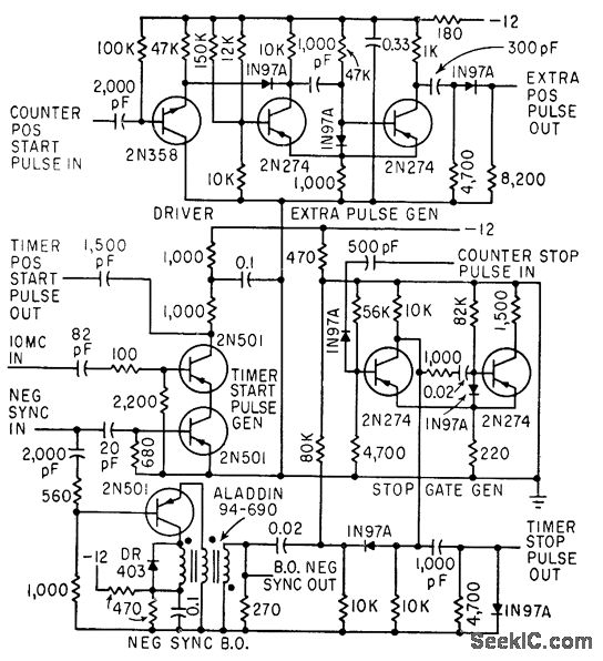
The timer start-pulse generator is a fast series-transistor coincidence circuit. The slope-gate generator is a one-shot multivibrator that prevents the 1N97A diode from passing the blocking oscillator's negative sync pulse until the multivibrator fires. This circuit is utilized to...