
IR auto digital thermostat

This temperature monitoring and control circuit employs various components to achieve its functionality. At its core, the AT89C51 microcontroller serves as the central processing unit, managing inputs from the LM35 temperature sensor and controlling outputs to the LCD display, relays, and alarm system. The LM35 sensor provides an analogue voltage proportional to the temperature, which is then converted into a digital signal using the ADC0804. The digital output from the ADC is fed into port 1 of the microcontroller for processing.
The LCD is connected to port 2 of the microcontroller, allowing the temperature readings to be displayed in real-time. Control signals for the LCD are routed through port 0, which also manages the activation of relays and the alarm. The ULN2003 driver circuit is utilized to interface the microcontroller with the relays, as the current output from the microcontroller pins is insufficient to directly drive the relays. The ULN2003 also provides necessary protection against back EMF generated by the inductive loads when the relays are switched off.
Power regulation is managed by two voltage regulators: a 7805 for the microcontroller and other low-power components, and a 7808 for providing power to the ULN2003 and relays. The LM555 timer is configured as a monostable multivibrator to generate a signal for the buzzer, which sounds an alarm when the temperature exceeds 40°C. The IR remote control functionality allows users to adjust the system settings remotely, with specific buttons assigned to control the relays and the alarm.
Overall, this circuit effectively combines temperature sensing, digital processing, and control mechanisms to maintain a safe operating temperature while providing user interaction through an IR remote.This circuit measures temperature in Celsius scale and displays it on an alphanumeric LCD screen. When temperature rise to 40 C an alarm is activated and at the same time a relay is also activated which drives a fan to keep the temperature at a level. Another feature of this circuit is that you can use the keys "1,2,3,4" of a Philips TV IR remote to turn on or off three relays, The key '4' is used to turn on or off the over temperature alarm.
The brain of this circuit is AT89C51 microcontroller. LM35 is a 3 pin chip which is easily available in TO-92 package. LM35 can sense temperature from 0 C to 100 C but it gives analogue output the microcontroller does not understand analogue data, so ADC0804 (analogue to digital converter) is used to convert it to digital form. This digital data is given to port 1 of microcontroller. (See the circuit diagram) this data is processed by microcontroller and temperature is displayed on lcd connected to port 2.The control pins of lcd are connected to port 0. port 0 also controls the relays and alarm. The ULN2003 chip is used to drive the relays because the microcontroller pins don't have enough current to drive them.
so relays cant be connected to microcontroller pins directly further more the relays are inductive load and reverse current is generated in them. Pin 1 to 7 are the inputs and 10to 16 are respective outputs. Pin 8 is ground and pin 9 is connected to the output of 7808 voltage regulator. The 7805 voltage regulator drives rest of the circuit. I used a standard buzzer driven by LM555 timer/Oscillator chip. The chip is wired as a monostable multivibrator and at its output (i.e. pin no 3) a buzzer is connected. Use any IR module and connect its Data out to pin 10 of microcontroller. The Relay connected to pin 13 of ULN2003 turns on when temp rises above 40 C so connect the fan to this relay.
🔗 External reference
Related Circuits
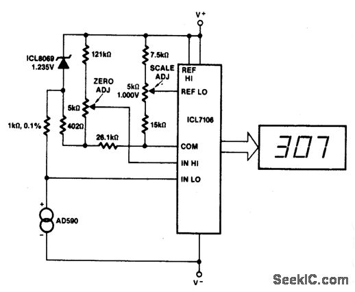
This circuit allows for zero adjustment as well as slope adjustment. The ICL8069 brings the input within the common-mode range, while the 5 K pots trim any offset at 218 °K (-55 °F) and set the scale factor. The...

The diagram illustrates the connections for the inputs and outputs of each operational amplifier from the power source, detailing how each operational amplifier is configured to operate individual light-emitting diodes (LEDs). It also includes calculations for determining each resistor...
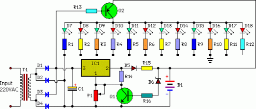
An emergency light system utilizing white LEDs, which provides several advantages: 1. It is highly bright due to the use of white LEDs. 2. The light activates automatically during a mains power failure and deactivates when mains power is...
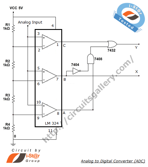
The process of converting an analog voltage into an equivalent digital signal is known as Analog to Digital Conversion (ADC). An ADC is an electronic circuit that converts its analog input to a corresponding binary value. The output depends...
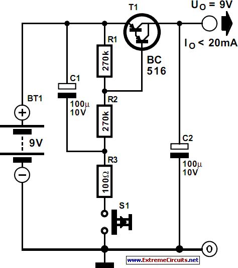
Battery-operated devices are increasingly prevalent, and manufacturers strive to minimize current consumption to enable prolonged operation on battery power. However, even minimal current draw can lead to battery depletion if the device is not powered off, resulting in a...
The copyright of this circuit is owned by Smart Kit Electronics. This document discusses improvements and modifications based on the original schematic. It describes a straightforward yet highly accurate and useful digital voltmeter designed as a panel meter, suitable...