
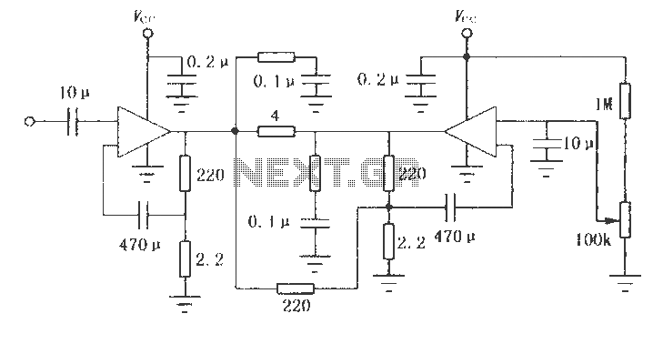
Digital High/Low Logic Tester Circuit diagram
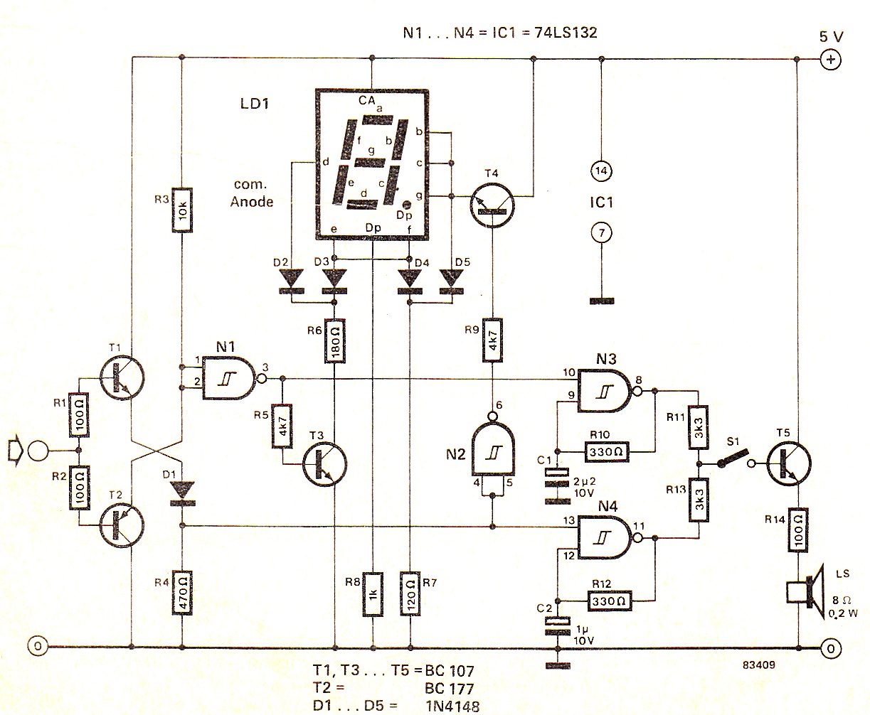
The circuit operates as a logic level indicator and audio feedback system, utilizing a combination of transistors, gates, and a loudspeaker to provide visual and auditory signals based on the input logic levels. The integration of a seven-segment display allows for clear visual representation of the input state, enhancing user interaction. The use of adjustable resistors for tone modification provides flexibility for users, enabling customization of the audio output to suit personal preferences. The design ensures that in the absence of a valid input signal, the circuit remains inactive, conserving power and preventing erroneous outputs. The inclusion of diodes in the circuit aids in controlling current flow and protecting sensitive components from voltage spikes, ensuring reliable operation across various input conditions. Overall, this circuit exemplifies a practical application of digital logic in a user-friendly format, suitable for educational purposes or as a diagnostic tool in electronic applications.When the input signal is logic 1, the display shows `H` and the loudspeaker emits a note which is an octave higher than the `low` tone. Operation of the circuit can be seen from the circuit diagram in figure 1 and the truth table in figure 2.
When the input signal is 1, transistor T1 conducts taking the input of gate N2 above the trigger threshold and the trigger output goes to logic 0. This is not our first high and low tester, but the present circuit offers something new: a seven-segment display which shows `H` or `L` and at the same time a small loudspeaker emits a corresponding tone. lf required, the loudspeaker can be switched on by means of S1. The switch can, of course, be omitted if the audio tone is always required. lf you have an ear for music, R10 and R12 may be replaced by a 220 Q resistor and a 2509 preset potentiometer so that the tone can be adjusted to your particular liking.
! When the supply is switched on, the decimal point of the display lights and indicates that the unit is ready For use. lf this is not the case, or an undefined signal is applied to the input, the display, apart from the decimal point, remains dark and the loudspeaker remains silent.
lf the input signal is logic O, the display shows `L` and the loudspeaker emits a low note. When the input signal is logic 0, T1 is cut off and T2 conducts. The voltage at the inputs of gates N1 and N2 are below the trigger threshold and both outputs are logic 1, switching on transistors T3 and T4; the emitter voltage of T4 rises and cuts off diodes D4 and D5. This causes a current to flow through segments d, e and f, diodes D2 and D3, resistor R6 and transistor T3.
With non-defined inputs (between 0. 8. . 2. 15 V) and an open circuit input, both input transistors are cut off, The output of N1 is then logic 0 and that of N2 is logic 1: no current can therefore flow through any of the segments. As regards the drive for the two oscillators, suffice it to say that during low inputs N3 is driven by the output of N1 and during high in- puts N4 is driven directly by T1.
Transistor T2 (PNP!) is cut off, the input of gate N1 is also above the trigger threshold and this trigger output is therefore also logic 0. Both switching transistors T3 and T4 are off and a current flows through the corresponding segments (b, c, e, f, g), diodes D4 and D5 and R7.
🔗 External reference
Related Circuits
Circuit Magic is an electrical circuits simulation program specifically designed for students teaching basics electronics, electrical laws & circuit theory. Unlike many electronic circuit analyzers, Circuit Magic can analyze circuits like a man. Circuits are simulated step by step,...
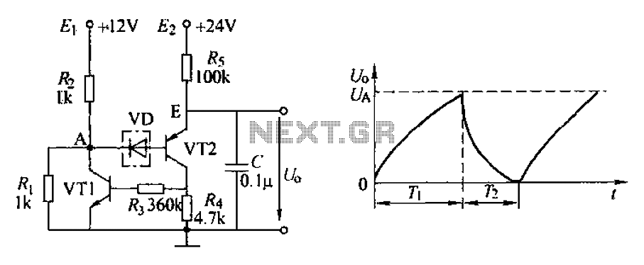
The application circuit depicted is a complementary sawtooth generator. In the schematic, VT1 is the transistor with a base current limiting resistor, which prevents excessive base current flow through the crystal tube. The resistor R4 acts as a bleeder...
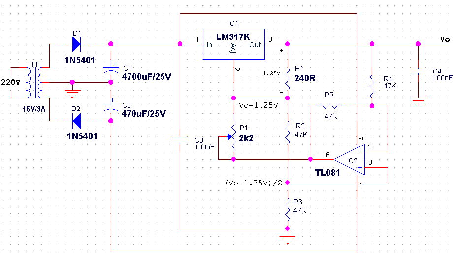
The LM317 is an adjustable, positive 3-terminal voltage regulator capable of supplying 100 mA (for RA87U control) or 1.5 A (for Order Code UF27E and N61CA) across an output voltage range of 1.2 V to 37 V. These voltage...
The LM2002 / 2002A is an audio power amplifier integrated circuit. The LM2002A features high voltage protection, with a maximum instantaneous power supply voltage of up to 40V, and comes in a 5-pin single in-line plastic package. This integrated...
Automatic Gain Control (AGC) is a circuit design that maintains a consistent level of amplification for sound or radio frequency signals. If the signal is too low, the AGC increases the gain to ensure the output remains at a...
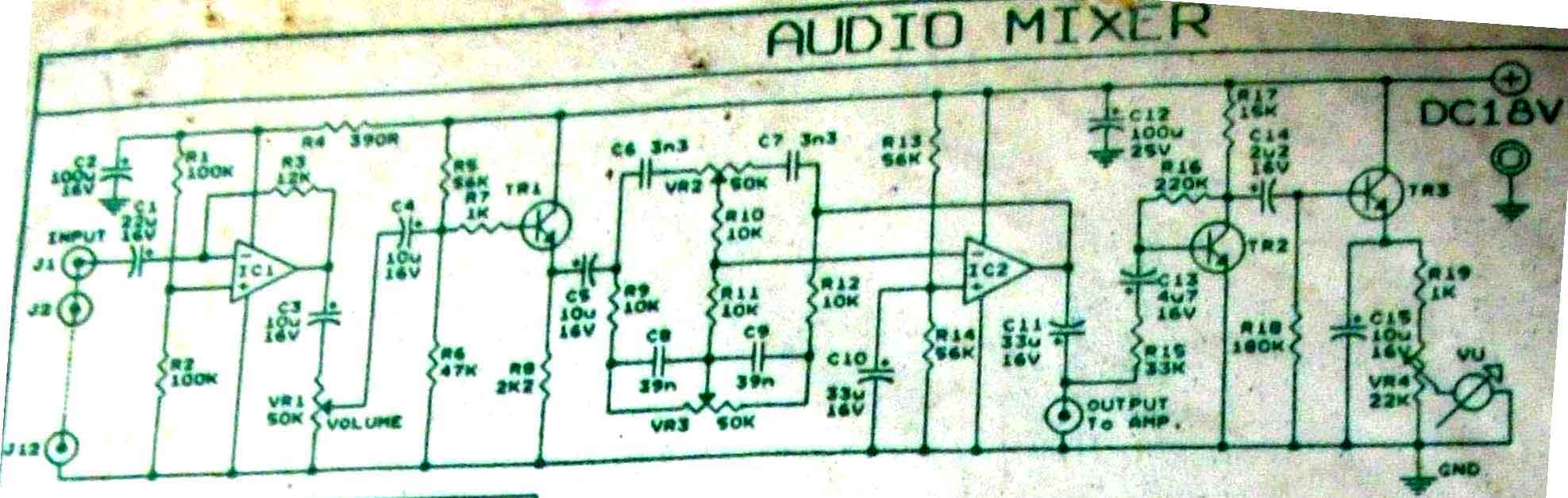
This is audio mixer circuit. The circuit is for one channel input, if you need, for example 5 channel mixer, then you need to build 5 similar circuits. The audio mixer circuit described is designed to handle a single channel...