
Automatic Gain Control - AGC Circuit

Automatic Gain Control (AGC) circuits are integral to various electronic applications, including audio processing, telecommunications, and broadcasting. The primary function of AGC is to automatically adjust the gain of an amplifier to maintain a steady output level despite varying input signal strengths. This is particularly useful in environments where signal levels fluctuate significantly, such as in radio receivers or during live audio performances.
An AGC circuit typically comprises several key components: a detector, an amplifier, and a feedback loop. The detector monitors the output signal level and compares it to a reference level. When the output deviates from this reference, the detector generates a control voltage that is fed back to the amplifier to adjust its gain. This feedback mechanism allows the AGC to respond dynamically to changes in the input signal.
The design of an AGC circuit can vary depending on the application. For instance, in audio systems, it is crucial to ensure that the gain adjustment is smooth to avoid distortion or abrupt changes in volume. In radio frequency applications, the AGC must respond quickly to changes in signal strength to maintain signal integrity.
The performance of an AGC circuit is characterized by parameters such as attack time, release time, and gain range. The attack time refers to how quickly the AGC responds to an increase in signal level, while the release time is the duration it takes to return to the original gain level after the signal decreases. The gain range indicates the minimum and maximum gain levels that the AGC can provide.
In summary, Automatic Gain Control circuits are essential for maintaining consistent output levels in various electronic systems, ensuring optimal performance across a range of signal conditions.Automatic Gain Control or AGC is a circuit design which maintain the same level of amplification for sound or radio frequency. If the signal is too low the.. 🔗 External reference
Related Circuits
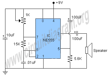
This project involves a 555 buzzer circuit utilizing the NE555 timer IC, which comes in an 8-pin DIP package and performs a wide variety of functions in electronic circuits. The circuit described will produce a buzzer sound when a...
A good performance is achieved with a two-wire connection for a double touch switch that can function even if there is a break in the left part of the line. This switch is designed for general lighting control, such...
The following circuit illustrates a curtain control circuit diagram. This circuit is based on the 555 integrated circuit (IC). Features include a switch for manual control, the IC, and additional components. The curtain control circuit utilizes the 555 timer IC...
The circuit output voltage can be continuously adjusted from zero to its maximum value. The baseline is established by a constant current sourced from the auxiliary power supply circuit. The reference current of 500 microamperes can be fine-tuned to...
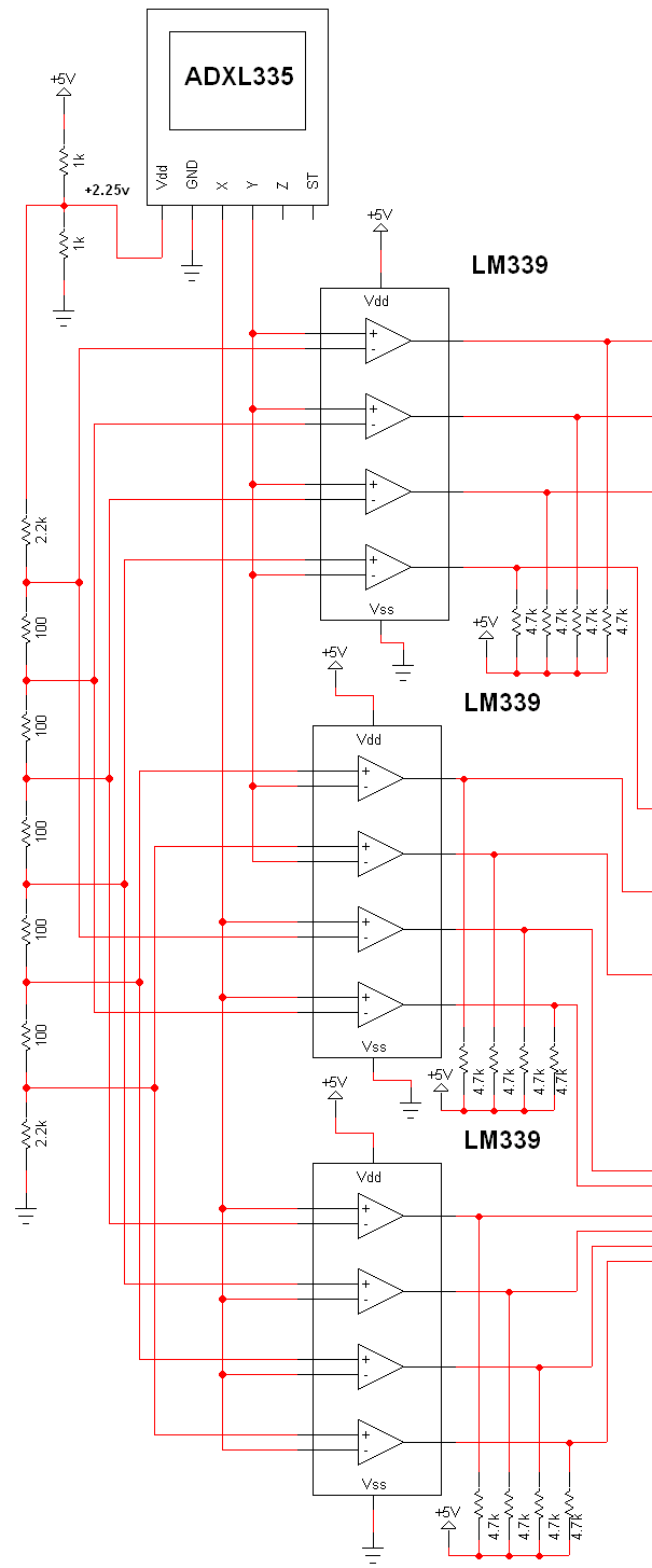
The schematic for this project is extensive, and the complete schematic is displayed below. It is divided into two sections: the analog and digital sections. The schematic illustrates the analog-to-digital conversion circuit, which includes 12 comparators—6 for the X-axis...
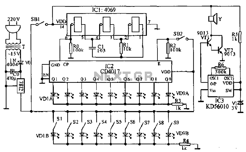
This document presents a principle circuit for electronic games. The main circuit operates in conjunction with the host through the reset button SB2, while the indicators VD1A-VD9A remain off. Prizes, for example, five, are determined by the number of...