
VU Meter with Audio Mixer circuit
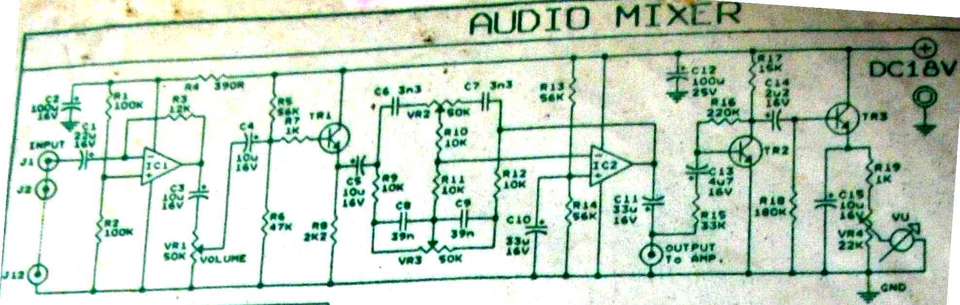
The audio mixer circuit described is designed to handle a single channel input. It is important to note that to create a multi-channel mixer, such as a five-channel mixer, five identical circuits must be constructed and integrated. Each circuit will typically consist of components that include operational amplifiers (op-amps), resistors, capacitors, and potentiometers.
The basic configuration of a single-channel audio mixer circuit may involve an op-amp configured as a non-inverting amplifier to boost the audio signal. The input audio signal is fed into the non-inverting terminal of the op-amp, while the inverting terminal is connected to a feedback resistor network, which sets the gain of the amplifier.
To allow for volume control, a potentiometer may be placed in series with the input signal. This allows the user to adjust the level of the input signal before it is amplified. Additionally, capacitors can be used for coupling, ensuring that only the AC audio signal passes through while blocking any DC offset that may be present.
For a multi-channel configuration, each channel would follow the same design principles, with individual volume controls and amplification stages. The outputs of each channel can then be mixed together at a summing point, which may also use an op-amp to combine the signals. The final output can be sent to a power amplifier or directly to speakers, depending on the application.
Overall, the construction of a multi-channel audio mixer requires careful attention to the layout and component values to ensure minimal noise and distortion, as well as proper matching of input and output impedances for optimal performance.This is audio mixer circuit. The circuit is for one channel input, if you need, for example 5 channel mixer, then you need to build 5 similar circuits. 🔗 External reference
Related Circuits
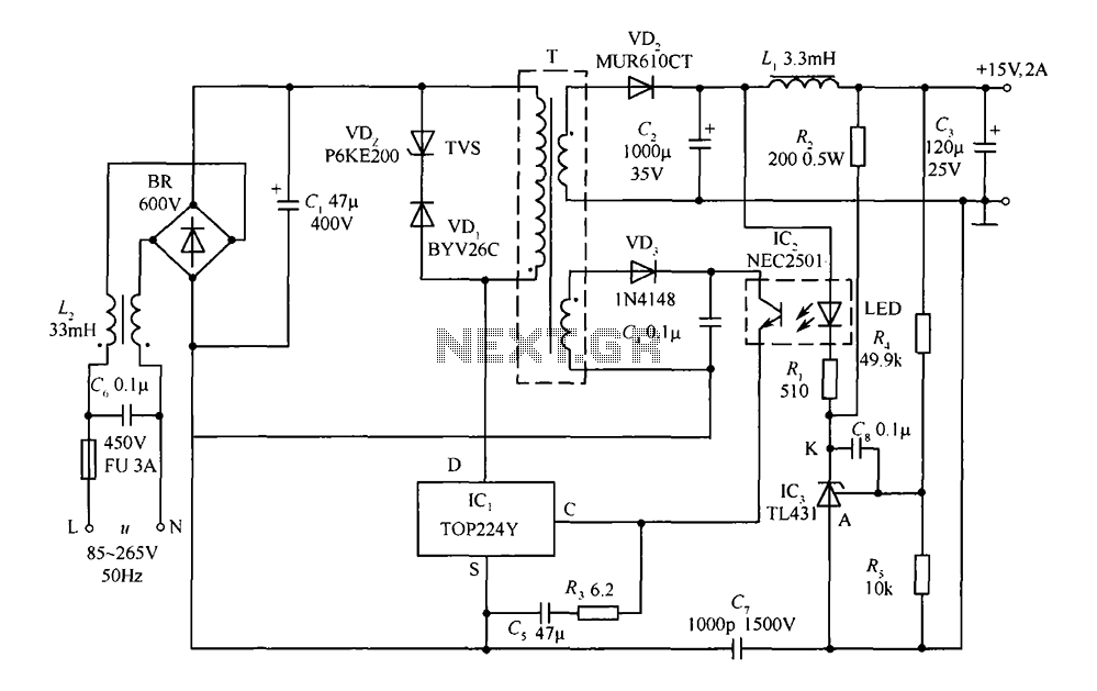
This circuit comprises a 15V TOP224Y, 2A output DC switching power supply. It utilizes three integrated circuits: IC1 is a monolithic regulator (TOP224Y), IC2 is an optocoupler (NEC2501), and IC3 is a precision voltage reference (TL431). The TL431 (IC3)...
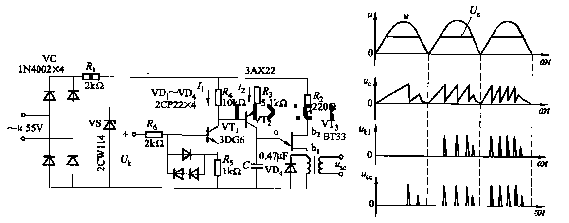
Due to the increased level of the transistor amplifier circuit, the control circuit's performance in Figure 16-6 is more sensitive and can accept input control signals superimposed on others (such as voltage, current, and speed feedback signals) to meet...
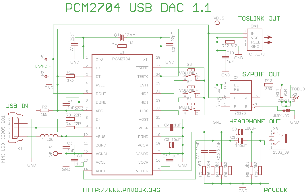
High-quality DAC converter from USB to S/PDIF. The circuit utilizes the PCM2704 chip, which was provided as a sample by Texas Instruments. It features an analog output for headphones and a digital S/PDIF output with both electrical and optical...
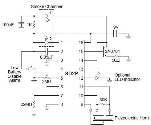
This smoke detector circuit diagram is based on the SD2 CMOS Photo-Electric Smoke Detector Integrated Circuit manufactured by Supertex Inc. It includes almost all the necessary components to build a simple and highly efficient smoke detector project. The LED...
The circuit principle involves using a current transformer for current sensing due to the large AC power load of computers. This setup detects whether there is current in the power line, enabling the determination of its status. The LM393...
The circuit operates at 380V for air flow. Power is supplied through a step-down transformer, which rectifies the output to 9V DC. When the pump operates correctly, a button labeled 'S' is activated. The circuit utilizes a TWH8778 component....
Warning: include(partials/cookie-banner.php): Failed to open stream: Permission denied in /var/www/html/nextgr/view-circuit.php on line 713
Warning: include(): Failed opening 'partials/cookie-banner.php' for inclusion (include_path='.:/usr/share/php') in /var/www/html/nextgr/view-circuit.php on line 713