
Digital Mains Failure/Resumption Alarm

The digital mains failure and resumption alarm circuit is designed to monitor the status of the mains power supply. It employs an optocoupler to provide electrical isolation between the high-voltage mains and the low-voltage control circuitry. The primary function of the circuit is to detect when the mains power is interrupted and to trigger an alarm when this condition occurs.
The circuit typically consists of several key components:
1. **Optocoupler**: This component plays a crucial role in isolating the high-voltage side from the low-voltage control circuit. When the mains supply is present, the optocoupler is activated, allowing current to flow through its LED, which in turn activates the phototransistor on the output side.
2. **Microcontroller or Comparator Circuit**: In more advanced designs, a microcontroller or a comparator may be used to monitor the output from the optocoupler. This component can be programmed to determine the state of the mains supply and decide when to trigger the alarm.
3. **Alarm Mechanism**: Upon detection of a mains failure, the circuit activates an alarm mechanism. This could be a simple buzzer or a more complex sound-generating device, depending on the design requirements. The alarm will typically sound for a predetermined duration or until the mains power is restored.
4. **Power Supply**: A separate power supply is often required for the low-voltage side of the circuit, ensuring that the alarm system remains operational even when the mains power is absent.
5. **Indicators**: Visual indicators such as LEDs can be incorporated to provide immediate feedback on the status of the mains power. For example, a green LED may indicate normal operation, while a red LED may illuminate during a mains failure.
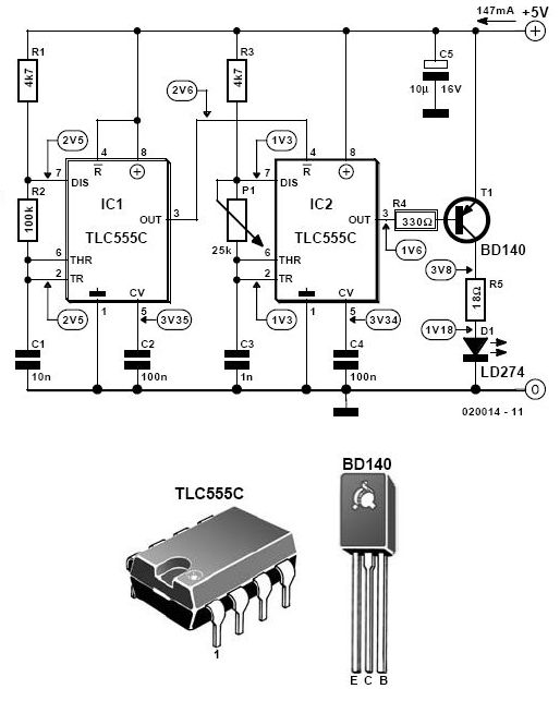
The schematic diagram of this circuit would illustrate the interconnections between these components, detailing how the optocoupler interfaces with the control circuitry and the alarm mechanism. It is essential to ensure that all components are rated appropriately for their respective voltage and current levels to maintain safety and reliability in the circuit's operation.Digital Mains Failure / Resumption Alarm use optocoupler and produce sound.circuit diagram with description of digital mains failure various alarm cirucit. 🔗 External reference
Related Circuits
The water tank overflow liquid level sensor alarm circuit is a straightforward electronics project suitable for school students. Previous discussions have covered numeric water level indicators and water level controller circuits, which are more complex and intended for engineering...

Often the need to control light switch on the instrument. If napájíme LED source of low DC voltage sufficient to classify a series of LED-resistor of appropriate resistance. Another situation occurs, if a small supply available, or to indicate...
This infrared alarm barrier is designed to detect individuals passing through doorways, corridors, and small gates. The transmitter emits an invisible beam of infrared light. When this beam is interrupted by a person, a buzzer connected to the receiver...
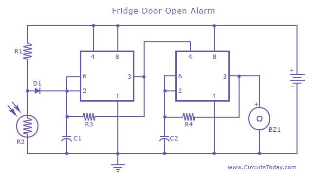
Fridge Door Alarm circuit or a Refrigerator door open alarm using 555 Timer IC, which produces an audible alarm if the door is left open for a preset time. The Fridge Door Alarm circuit utilizes a 555 Timer integrated circuit...
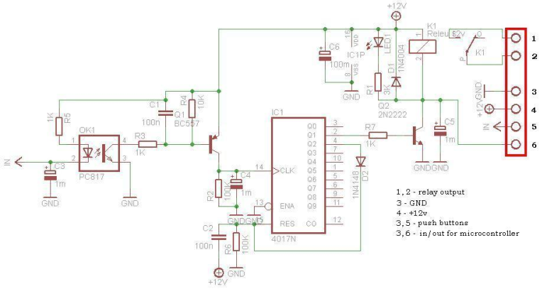
This circuit is operating the room illuminates. The basic component of the circuit is a IC1 (CD4017). Push buttons room are connected by normally wired to the circuit. All circuit is separately by optocoupler, which means that the circuit...
The State Jal Boards provide water for a limited duration each day. The timing of water supply is determined by the management, and the public is not informed of this schedule. The operation of State Jal Boards typically involves a...