
Mains Detector Relay with CD4017
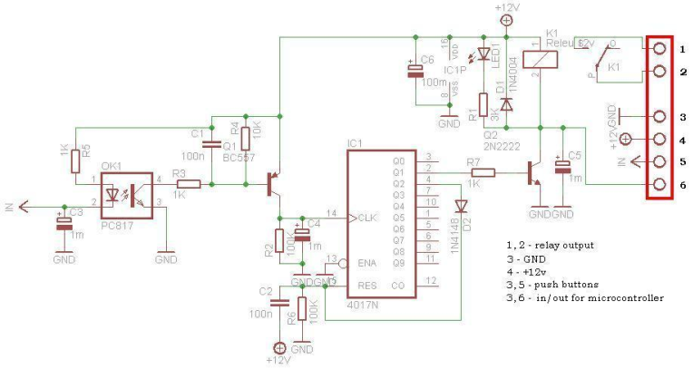
The C2 - R6 component keep the Reset pin to +12V, when the circuit is powering, until the C2 loaded at 12V.
From transistor Q2 colector is IN/OUT for use in to microcontroller system (GSM remote control, WEB control, etc.). When use as IN, microcontroller system can put to GND Q2 colector, and relay is ON. Or the colector is use as OUT, signal obtained say the microcontroller system, if the relay is ON or OFF. In the first place, a relay is like a switch to a coil assembly. This switch is activated when electricity is applied to the coil. With a common relay, the electricity must be continuously applied to the coil to maintain the contacts, but the impulse relay "remembers" and only requires a momentary application of electricity. Stated differently, apply pulse of electricity to the coil to turn on the relay contacts, apply another pulse of electricity to turn off the relay contacts.
So, impulse relay use it for to turn on a lamp with pushbuttons and not toggle switches. What is really neat is connecting several momentary pushbuttons in parallel and placing them in different locations. I can turn on the lamp in one room, and turn it off from a different room, because it was the relay that was providing electricity to the lamp, not the switch. A digital impulse relay is a electronic circuit that mimics perfect the all functions of a impulse relay with ratchet mechanism: the first press to the button turns the relay on and the second press turns it off, and relay in the circuit operating room illuminates. Particularity of this circuit is that it can be used in a centralized system for home automation. Another advantage is lower price compared with that of the impulse relay with ratchet mechanism. Digital impulse relay is immune to electrical noise, connection between buttons and circuit can be achieved with unshielded cable and any length. The power supply for the circuit is DC 12V. In standby, when relay is OFF, digital impulse relay consume 0V. Otherwise, when relay is ON, consume depend of 12V relay current.
The described circuit primarily utilizes a CD4017 decade counter integrated circuit (IC1) to manage the operation of a relay based on pushbutton inputs. The pushbuttons are connected in a normally open configuration, allowing the circuit to remain inactive until a button is pressed. Each button press triggers an optocoupler that isolates the control circuit from potential electrical noise, ensuring reliable operation even in noisy environments.
The optocoupler's output is processed by a BC557 transistor (Q1), which amplifies the signal and feeds it to the clock input (pin 14) of the CD4017. Each clock pulse increments the counter, causing the output pin 2 to transition high, activating a 12V relay through the 2N2222 transistor (Q2). The relay's operation is indicated by an LED (LED1), which lights up when the relay is engaged.
A diode (D1) is employed across the relay coil to protect the circuit from back EMF generated when the relay is deactivated. The circuit also incorporates a reset mechanism; upon pressing the button again, the counter decrements, turning the relay off and setting pin 4 high. A second diode (D2) can reset the counter to its initial state, allowing for repeated cycles of operation with subsequent button presses.
Capacitor C2 and resistor R6 serve to maintain the reset pin of the CD4017 at a stable +12V during power-up until the capacitor is charged. This ensures the circuit is ready for operation immediately after being powered.
The collector of Q2 can be configured for use with a microcontroller, enabling integration into larger automation systems such as GSM or web-controlled applications. In this configuration, the collector can signal the microcontroller whether the relay is engaged or disengaged, facilitating remote control capabilities.
Overall, this digital impulse relay circuit is particularly advantageous for applications requiring centralized control of lighting systems, offering flexibility, ease of installation with unshielded cabling, and cost-effectiveness compared to traditional mechanical relays. The low power consumption in standby mode further enhances its suitability for energy-efficient designs.This circuit is operating the room illuminates. The basic component of the circuit is a IC1 (CD4017). Push buttons room are connected by normally wired to the circuit. All circuit is separately by optocoupler, which means that the circuit is immune to electrical noise that can come on cable that connects with push buttons. First any button push put to GND the optocoupler IN. The output signal from optocoupler is amplified by transistor Q1 (BC557) together by C1, R3, R4 circuit.
The amplified signal is attack to clock pin 14 of decade counter IC1 (CD4017), the counter advances by 1, pin 2 goes high and relay is ON. Transistor Q2 (2N2222) connected to pin 2 of IC1 drives 12V relay. Diode 1N4004 (D1) acts as a freewheeling diode. LED1 indicate the ON/OFF status. Second any button press, the IC1 advances by 1, pin 2 goes low, relay is OFF, and pin 4 goes high. If we connect by diode D2, pin 4 to Reset pin of CD4017, the counter is going back to the initial condition, and is ready to get another button press, to turn the relay ON. The C2 - R6 component keep the Reset pin to +12V, when the circuit is powering, until the C2 loaded at 12V.
From transistor Q2 colector is IN/OUT for use in to microcontroller system (GSM remote control, WEB control, etc.). When use as IN, microcontroller system can put to GND Q2 colector, and relay is ON. Or the colector is use as OUT, signal obtained say the microcontroller system, if the relay is ON or OFF.
In the first place, a relay is like a switch to a coil assembly. This switch is activated when electricity is applied to the coil. With a common relay, the electricity must be continuously applied to the coil to maintain the contacts, but the impulse relay "remembers" and only requires a momentary application of electricity. Stated differently, apply pulse of electricity to the coil to turn on the relay contacts, apply another pulse of electricity to turn off the relay contacts.
So, impulse relay use it for to turn on a lamp with pushbuttons and not toggle switches. What is really neat is connecting several momentary pushbuttons in parallel and placing them in different locations. I can turn on the lamp in one room, and turn it off from a different room, because it was the relay that was providing electricity to the lamp, not the switch.
A digital impulse relay is a electronic circuit that mimics perfect the all functions of a impulse relay with ratchet mechanism: the first press to the button turns the relay on and the second press turns it off, and relay in the circuit operating room illuminates. Particularity of this circuit is that it can be used in a centralized system for home automation. Another advantage is lower price compared with that of the impulse relay with ratchet mechanism. Digital impulse relay is immune to electrical noise, connection between buttons and circuit can be achieved with unshielded cable and any length.
The power supply for the circuit is DC 12V. In standby, when relay is OFF, digital impulse relay consume 0V. Otherwise, when relay is ON, consume depend of 12V relay current. 🔗 External reference
Related Circuits
The metal detector circuit comprises an oscillator and a sound-light alarm circuit. The oscillator circuit includes an inductor (L), a capacitor (C1), a sensor switch integrated circuit (IC1) that integrates the oscillator, detector, comparator circuit, and peripheral components. The...
A live-line detector is a circuit designed to identify the presence of a live mains conductor through capacitive coupling between the live conductor and the detection circuit. The live-line detector operates on the principle of capacitive coupling, which allows it...
Construct the compact stripboard relay shield for Arduino. Access the circuit diagram and download the associated software. Control two relays from a PC and utilize the PC to manage the on and off states of devices. The tiny stripboard relay...
The TEM, specifically the Jeol 2000fx model, is equipped with two additional detectors: a secondary electron detector for SEM imaging and a STEM detector located at the bottom of the microscope. As the system dates back to the 1980s,...
The circuit illustrates the use of a 555 Timer IC in an infrared (IR) detector configuration. It features a duty cycle of 0.8 milliseconds, a frequency of 120 Hz, and a peak current of 300 mA. The 555 Timer IC...

This circuit was designed for use in a hi-fi showroom, where a choice of speakers could be connected to a stereo amplifier for comparative purposes. The circuit serves as a speaker selector that facilitates the connection of multiple speakers to...