
AC MAINS LED indicator schematic

If you connect this capacitor to the voltage, current will flow through it 230/31831 = 0.0072 A. If you connect a capacitor in series with the LED bridge rectifier according to Figure 2, the stream has been substantially altered. In terms of functionality is more important often overlooked resistor R2. In practice, it is only rarely will switch on the device when the voltage is currently close to zero. Reflective nature can be calculated that half the time the phase conductor to zero even more effective than the reported 230 V. When your pilot light, it must be possible to charge capacitor C1. At this moment pass capacitor (and thus the LED) current pulse, which can be several orders of magnitude larger than the steady alternating current. The current pulse there will be a step change in power supply - for example, when you turn off appliances and a large collection. The current pulse is very short - not even visible light-emitting diode flashes - but also can damage the diodes. Most have suffered light-emitting diode, which I checked many years ago, when engaged in similar brightness light-emitting diode light gradually diminished, and after about half a year was barely noticeable. For the resistor R2, I tested the resistance from 470 to 1000 ohms. The current pulse is limited to a few hundred milliamps and voltage drop on this resistor is in steady state so small it does not affect the function of the circuit. It is necessary to mention the involvement according to Figure 4. Instead of rectifying diodes can also engage light-emitting diode. However, since the current through the LED only when one half period, the LED is lit for the same need to use a capacitor with twice the capacity.
The used components. Capacitor voltage must be at least 400, preferably 630 V capacitors are suitable for AC 250 V (see for example, GM's electronic catalog). Resistors can be miniaturized as well as diodes (KA.., KY .., 1N4148, etc.).
In conclusion it can again be noted that the involvement of Figure 2 and 3 can also be used as a simple rechargeable NiCad, replacing a light-emitting diode with one or more articles. In the same way he was involved in a battery charger lamp, produced by the team mechanics. Charging current is similar to the light-emitting diodes, only about 7 mA per 100 nF capacitor C1, and therefore more suitable for cells with less capacity. Resistor R1 has a single mission - to off kontrolce capacitor and prevent the annoying "digs" in handling the device off. It is completely indifferent to whether it is plugged into the circuit according to Figure 2 or 3. It may be deleted if the capacitor provided by other means, such as connecting LEDs in parallel to the primary winding of the transformer.
The circuit described involves the use of both resistors and capacitors to manage the current flow through light-emitting diodes (LEDs). An LED typically operates at a lower voltage and requires a specific current to function effectively. The inclusion of a resistor in series with the LED serves to limit the current, preventing damage to the LED from excessive current flow. The use of a capacitor in the circuit allows for a more efficient current regulation, as the capacitor can store and release energy, smoothing out the current flow to the LED.
The relationship between the capacitor's reactance (Xc), frequency (f), and capacitance (C) is critical in determining how the circuit will behave under different conditions. The calculated reactance for a 100 nF capacitor at a standard frequency (e.g., 50 Hz) leads to a specific current flow that can be predicted mathematically. This established behavior becomes particularly important when discussing the impact of transient pulses generated when switching devices on and off, which can pose a risk to the longevity of the LED.
The circuit's design also considers the need for a protective resistor (R2) to mitigate the effects of these transient pulses. The values of resistors can be adjusted based on testing to find the optimal balance between limiting current and ensuring the LED remains functional during normal operation.
Additionally, the circuit can be adapted for use with rechargeable batteries, showcasing its versatility. The same principles apply when charging NiCad batteries, with current levels adjusted to suit the battery's specifications. The design's simplicity and reliability make it a practical solution for various applications, both in lighting and charging circuits.
In summary, the described circuit effectively combines capacitors and resistors to manage LED operation and protect against transient conditions, while also offering adaptability for battery charging applications.Often the need to control light switch on the instrument. If napájíme LED source of low DC voltage sufficient to classify a series of LED-resistor of appropriate resistance. Another situation occurs, if a small supply available, or to indicate when the voltage needed before the safety equipment supplied.
In such cases, has been used for many years with the glow resistor ballasts, see Figure 1 . This solution is not very elegant, but it is reliable and relatively inexpensive. Network lights, we can produce LED. Use a resistor, however, precipitation in this case is not appropriate. While neon is an operating voltage of 70-150 V and current of only a fraction of mA, standard LED current requires about 10 mA at a voltage of about 2 V. Involvement with LED lights is the figure 2. Consider, however, this involvement in more detail. The joke is that the current through the LEDs is limited by the resistor, but the capacitor capacitance. Capacitance can be chosen so that the current through it can directly regulate the power LED. Since the current leads voltage by 90 degrees, does not arise in the (ideal) capacitor is no capacitor power loss and does not heat.
Reactance of the capacitor can be easily calculated where Xc is capacitive reactance in ohms, pi pi (3.14 ..), f frequency in Hz and C capacitance in farad. Capacitor with a capacity of 100 nF will have the network frequency reactance 1 / (2.3, 14.50.10 -7) = 31,831 ohms.
If you connect this capacitor to the voltage, current will flow through it 230/31831 = 0.0072 A. If you connect a capacitor in series with the LED bridge rectifier according to Figure 2 , the stream has been substantially altered. In terms of functionality is more important often overlooked resistor R2. In practice, it is only rarely will switch on the device when the voltage is currently close to zero.
Reflective nature can be calculated that half the time the phase conductor to zero even more effective than the reported 230 V. When your pilot light, it must be possible to charge capacitor C1. At this moment pass capacitor (and thus the LED) current pulse, which can be several orders of magnitude larger than the steady alternating current.
The current pulse there will be a step change in power supply - for example, when you turn off appliances and a large collection. The current pulse is very short - not even visible light-emitting diode flashes - but also can damage the diodes.
Most have suffered light-emitting diode, which I checked many years ago, when engaged in similar brightness light-emitting diode light gradually diminished, and after about half a year was barely noticeable. For the resistor R2, I tested the resistance from 470 to 1000 ohms. The current pulse is limited to a few hundred milliamps and voltage drop on this resistor is in steady state so small it does not affect the function of the circuit.
It is necessary to mention the involvement according to Figure 4 . Instead of rectifying diodes can also engage light-emitting diode. However, since the current through the LED only when one half period, the LED is lit for the same need to use a capacitor with twice the capacity. The used components. Capacitor voltage must be at least 400, preferably 630 V capacitors are suitable for AC 250 V (see for example, GM's electronic catalog).
Resistors can be miniaturized as well as diodes (KA.., KY .., 1N4148, etc.). In conclusion it can again be noted that the involvement of Figure 2 and 3 can also be used as a simple rechargeable NiCad, replacing a light-emitting diode with one or more articles. In the same way he was involved in a battery charger lamp, produced by the team mechanics. Charging current is similar to the light-emitting diodes, only about 7 mA per 100 nF capacitor C1, and therefore more suitable for cells with less capacity.
Resistor R1 has a single mission - to off kontrolce capacitor and prevent the annoying "digs" in handling the device off. It is completely indifferent to whether it is plugged into the circuit according to Figure 2 or 3 . It may be deleted if the capacitor provided by other means, such as connecting LEDs in parallel to the primary winding of the transformer.
🔗 External reference
Related Circuits
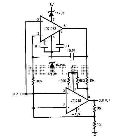
It uses the LT1052 and LT1028. The power supply should be dual with ±15V at 500mA. This is an ideal stabilized amplifier. The circuit utilizes the LT1052 and LT1028 operational amplifiers, which are known for their precision and stability. The...
The 2N388A transistors are inexpensive (approximately 18 cents when purchased in lots of five or more). The 2N5088 transistors are readily available from Mouser. Other components can typically be sourced from Radio Shack or local stores. To convert to...
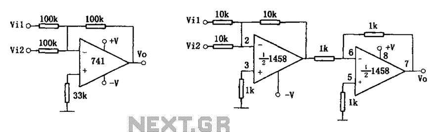
The common addition circuit is illustrated, with Figure (a) depicting the inverting adder circuit. The input-output relationship is expressed as Vo = -(Vi1 + Vi2). For phase addition, the circuit shown in Figure (b) can be utilized, with the...
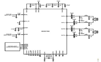
This is a typical stereo application circuit schematic of the ADAU1592, a 2-channel, bridge-tied load (BTL) switching audio power amplifier. The ADAU1592 can be utilized in flat panel televisions, PC audio systems, and mini-component applications. The ADAU1592 is designed to...
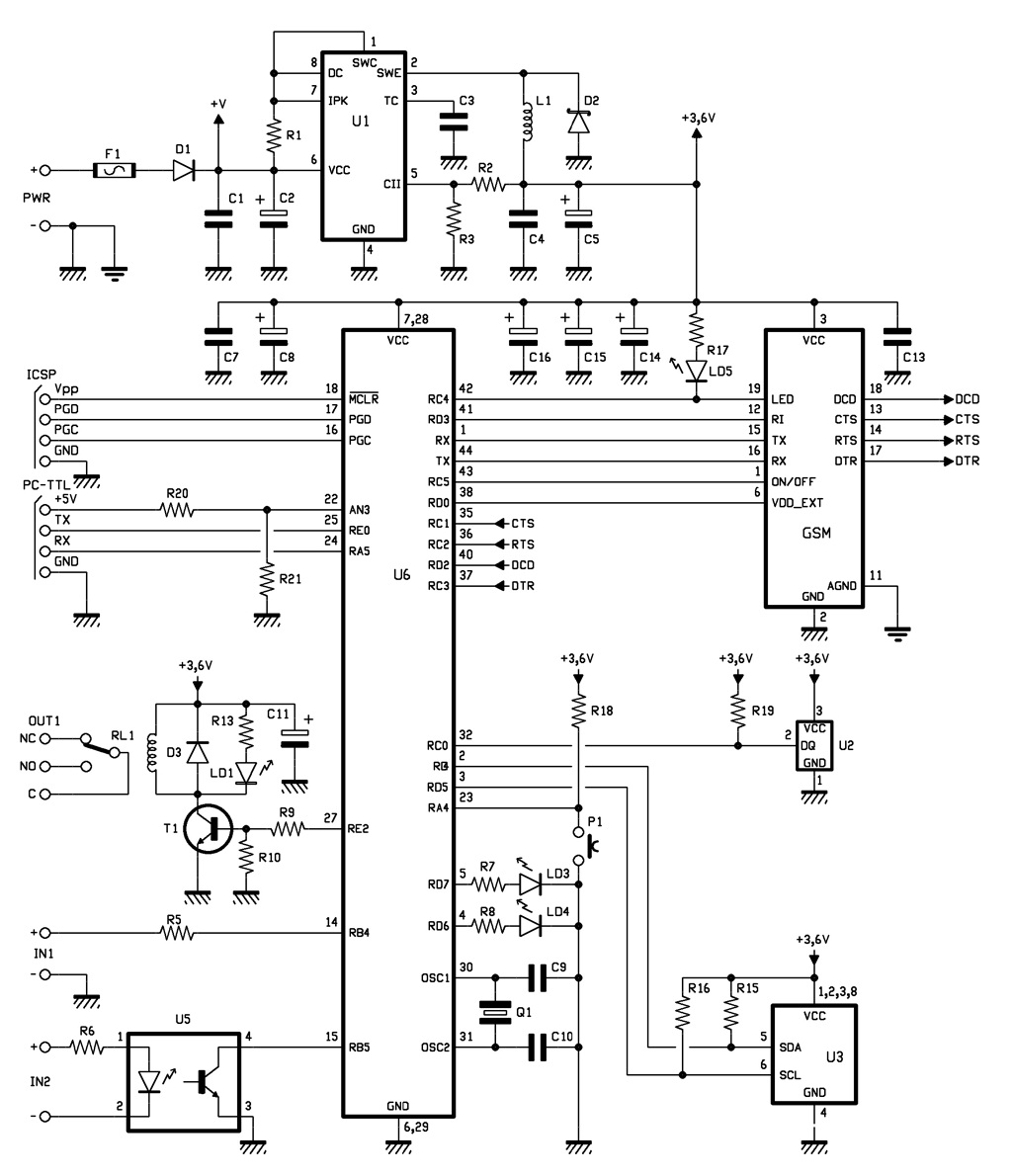
The complete GSM thermostat is controlled by a Microchip PIC18F46K20-I/PT microcontroller, which is programmed with firmware to manage temperature regulation and facilitate communication with the GSM module. This module, referred to as GSM, is a compact board that contains...
Battery Indicator Circuit for the Caravan. This i-TRIXX circuit can prevent a lot of trouble for those who go on holiday in a caravan. It would be a significant damper on your holiday spirit when you are unprepared. The Battery...