
digital multimeter using 8051

The digital multimeter circuit design will utilize a microcontroller, such as an Arduino or a similar platform, to process the signals from the voltage and current sensors. The input stage will consist of a voltage divider to scale the input voltage to a safe level suitable for the microcontroller’s ADC (Analog-to-Digital Converter). For AC measurements, a rectifier circuit will be implemented to convert the AC voltage to a DC equivalent, allowing the microcontroller to read the value accurately.
For current measurements, a shunt resistor will be employed in series with the load, and the voltage drop across this resistor will be measured. The microcontroller will calculate the current using Ohm's law, taking into account the known resistance value. The microcontroller's firmware will be programmed in C, where functions will be defined to handle the input from the sensors, perform necessary calculations, and format the output to be displayed on the LCD.
The LCD will be configured to indicate the type of measurement being displayed (AC or DC) along with the units (A for current and V for voltage). This will involve creating a user interface that prompts the user to select the measurement type. The display logic will include conditional statements to differentiate between AC and DC readings based on the input signal characteristics.
In summary, the digital multimeter circuit will integrate voltage and current measurement capabilities, powered by a 9V battery, and will feature a user-friendly LCD interface. The modifications to the existing voltmeter project will allow for comprehensive measurement of both AC and DC signals across the specified ranges. The final assembly will ensure that all components are properly connected, and the firmware will be rigorously tested to ensure accurate readings and reliable performance.Build a digital multimeter that can measure dc/ac voltages up to 100V and dc/ac currents up to 1A. The circuit will be powered by 9v battery. I have decided to use the voltmeter from and modify it according to my needs. The problem is that after implementing the circuit, I only get half the value shown on the lcd (10v input, 5v on lcd)[SOLVED: I was suppose to connect to vcc not Vref/2] What could be the reason for this thank you @Experimenteruk everything works perfectly. Now I have to add a rectifier so I can measure AC voltage and current. I am going to post the finished project when it`s all done. Hi, I`m new here. I want to modifie the digital voltmeter project into a multimeter to measure 0-100 V AC and DC and 0-1 A. How can I modifie the c code to display on the LCD AC, DC, A, V 🔗 External reference
Related Circuits
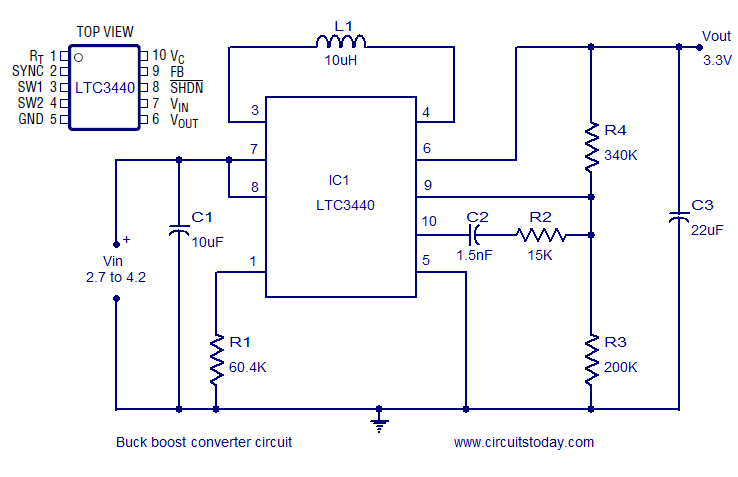
A simple and highly efficient buck-boost converter is implemented using the LTC3440 integrated circuit. The output voltage is set at 3.3V, while the input voltage range can vary from 2.7V to 4.2V. The LTC3440 is a synchronous buck-boost converter designed...
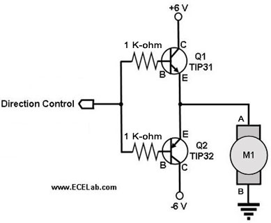
The following circuit illustrates a two-transistor DC motor driver circuit diagram. This circuit utilizes the TIP32 transistor. Features: operates in... The two-transistor DC motor driver circuit is designed to control the operation of a DC motor using two NPN transistors,...
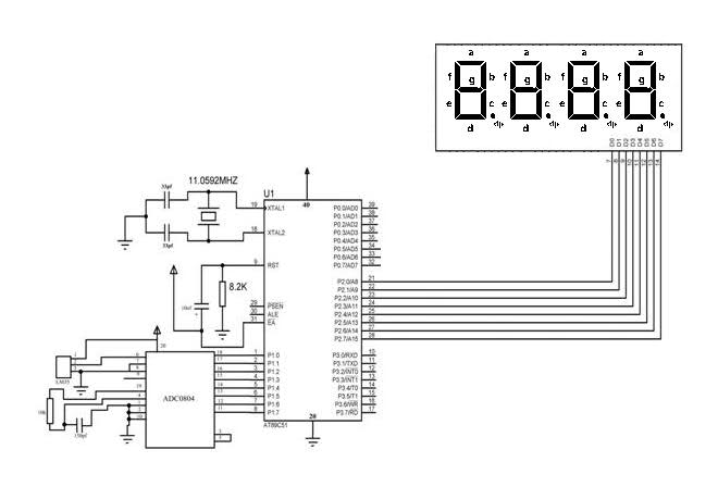
The temperature sensor was connected to 8 LEDs provided with the DeccanRobots package, successfully displaying the temperature in binary format. However, when attempting to use a microcontroller with a program designed to output the temperature on 4 seven-segment displays...
The power is measured by the circuit AD8307 over a 50 ohm dummy load. An A/D converter of 12 bit converts the analog output from the AD8307 to a digital number. Since the AD is a 12 bit A/D,...
This is an easy-to-build yet highly accurate digital voltmeter designed as a panel meter for use in DC power supplies or any application requiring precise voltage indication. The circuit utilizes the CL7107 ADC (Analog to Digital Converter) IC manufactured...
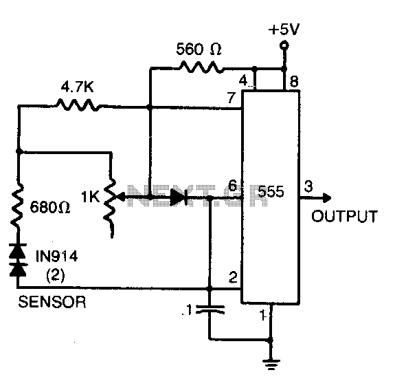
The sensor comprises two series-connected 1N914 diodes, which are part of the circuit of a 555 multivibrator. When wired as illustrated, the output pulse rate is proportional to the temperature of the diodes. This output is then fed into...