
led display digital voltmeter
The digital voltmeter circuit operates by employing precise electronic components to ensure accuracy and reliability in voltage measurement. The integration of the CL7107 ADC IC simplifies the design while maintaining high performance. The dual slope method utilized by the ADC allows for effective noise rejection, which is critical in achieving stable readings in varying electrical environments. The choice of a common anode configuration for the LED displays facilitates straightforward interfacing with the IC while providing clear visibility of the voltage readings.
The resistors and capacitors employed in the circuit serve specific functions that enhance the overall performance. For instance, the integration stage, managed by C3 and R5, plays a crucial role in smoothing the input voltage signal, thereby ensuring that transient fluctuations do not affect the reading. The calibration components (R2 and P1) allow for fine-tuning of the circuit during setup, ensuring that the voltmeter provides accurate readings across its operational range. The design emphasizes minimal component count while maximizing functionality, making it suitable for various applications where precise voltage monitoring is essential.
Overall, this digital voltmeter design is a practical solution for engineers and technicians requiring accurate voltage measurements in laboratory settings, educational environments, or industrial applications. Its straightforward construction and reliable performance make it a valuable tool for numerous electronic projects.This is an easy to build, but nevertheless very accurate and useful digital voltmeter. It has been designed as a panel meter and can be used in DC power supplies or anywhere else it is necessary to have an accurate indication of the voltage present. The circuit employs the ADC (Analogue to Digital Converter) I. C. CL7107 made by INTERSIL. This IC i ncorporates in a 40 pin case all the circuitry necessary to convert an analogue signal to digital and can drive a series of four seven segment LED displays directly. The circuits built into the IC are an analogue to digital converter, a comparator, a clock, a decoder and a seven segment LED display driver.
The circuit as it is described here can display any DC voltage in the range of 0-1999 Volts. In order to understand the principle of operation of the circuit it is necessary to explain how the ADC IC works. This IC has the following very important features: An Analogue to Digital Converter, (ADC from now on) is better known as a dual slope converter or integrating converter.
This type of converter is generally preferred over other types as it offers accuracy, simplicity in design and a relative indifference to noise which makes it very reliable. The operation of the circuit is better understood if it is described in tw1o stages. During the first stage and for a given period the input voltage is integrated, and in the output of the integrator at the end of this period, there is a voltage which is directly proportional to the input voltage.
At the end of the preset period the integrator is fed with an internal reference voltage and the output of the circuit is gradually reduced until it reaches the level of the zero reference voltage. This second phase is known as the negative slope period and its duration depends on the output of the integrator in the first period.
As the duration of the first operation is fixed and the length of the second is variable it is possible to compare the tw1o and this way the input voltage is in fact compared to the internal reference voltage and the result is coded and is send to the display. All this sounds quite easy but it is in fact a series of very complex operations which are all made by the ADC IC with the help of a few external components which are used to configure the circuit for the job.
In detail the circuit works as follows. The voltage to be measured is applied across points 1 and 2 of the circuit and through the circuit R3, R4 and C4 is finally applied to pins 30 and 31 of the IC. These are the input of the IC as you can see from its diagram. (IN HIGH & IN LOW respectively). The resistor R1 together with C1 are used to set the frequency of the internal oscillator (clock) which is set at about 48 Hz.
At this clock rate there are about three different readings per second. The capacitor C2 which is connected betw1een pins 33 and 34 of the IC has been selected to compensate for the error caused by the internal reference voltage and also keeps the display steady. The capacitor C3 and the resistor R5 are together the circuit that does the integration of the input voltage and at the same time prevent any division of the input voltage making the circuit faster and more reliable as the possibility of error is greatly reduced.
The capacitor C5 forces the instrument to display zero when there is no voltage at its input. The resistor R2 together with P1 are used to adjust the instrument during set-up so that it displays zero when the input is zero. The resistor R6 controls the current that is allowed to flow through the displays so that there is sufficient brightness with out damaging them.
The IC as we have already mentioned above is capable to drive four common anode LED displays. The three rightmost displays are connected so that they can display all the numbers from 0 to 9 while the first from the left can only display the number 1 and when the voltage is negative the «- « sign. The w 🔗 External reference
Related Circuits

The Atmega8 microcontroller from Atmel features numerous digital and analog input/output lines, making it an ideal choice for developing various measurement equipment. It is essential to have the GCC AVR programming environment installed, as outlined in the article "Programming...
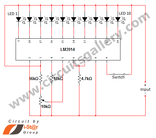
In various situations, it is necessary to indicate the amount of battery charge using methods such as LED dot displays or LED bar displays. This circuit utilizes the LM3914 integrated circuit to serve as a battery charge indicator with...
The lab project involves a BCD counter and a 7-segment display using the CD4510BMS presettable BCD Up/Down Counter. The objective is to count from 32 to 84, rather than the default range of 00 to 99. The current setup...
This LED circuit replicates the initial LED sequence currently utilized by FISA for Formula One racing. It can also be employed with slot car sets, such as HO scale AFX, Life Like, or Tyco sets, or used in communication-controlled...
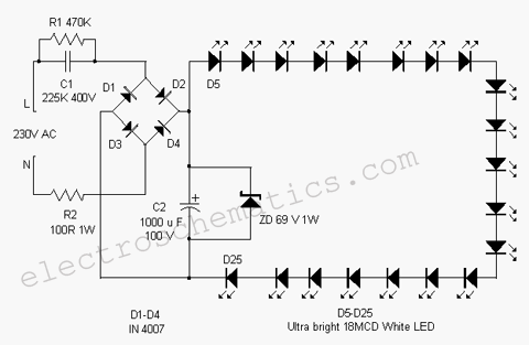
This white LED light illuminates the porch with cool white light. The circuit features a simple and energy-saving design. Its current consumption is practical. The white LED light circuit is designed to provide efficient illumination while minimizing energy usage. The...
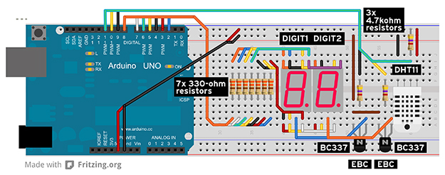
In Part 2 of the Arduino masterclass, a weather station is built to measure temperature in degrees Celsius and relative humidity as a percentage. New components and theory are introduced, and practical application is emphasized. While LEDs are effective...