
Two-Transistor DC Motor DriverCircuit Using The TIP32 Transistor
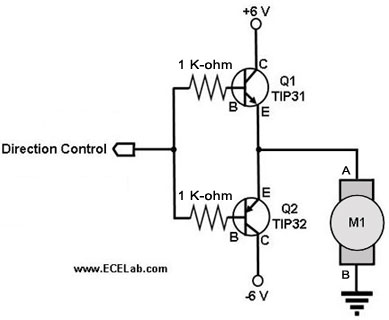
The two-transistor DC motor driver circuit is designed to control the operation of a DC motor using two NPN transistors, which function as switches. The TIP32, a PNP transistor, is often employed in this configuration due to its capability to handle higher currents and voltages, making it suitable for driving motors.
In this circuit, the two NPN transistors are connected in a complementary push-pull configuration. When a control signal is applied to the base of the first NPN transistor, it turns on, allowing current to flow from the power supply through the motor and into the collector of the first transistor. This action causes the motor to rotate in one direction. Simultaneously, the second NPN transistor remains off, preventing current from flowing through it.
When the control signal is switched to the second transistor, it turns on, redirecting the current flow through the motor in the opposite direction, effectively reversing its rotation. This capability provides bidirectional control of the motor, which is essential for applications requiring precise movement, such as robotics or automated systems.
The circuit typically includes additional components, such as diodes for flyback protection, which safeguard the transistors from voltage spikes generated when the motor is switched off. Capacitors may also be included to filter out noise and stabilize the power supply.
Overall, this two-transistor DC motor driver circuit is a robust solution for controlling DC motors, offering simplicity in design while providing effective control over the motor's direction and speed.The following circuit shows about Two-Transistor DC Motor Driver Circuit Diagram . This circuit using the TIP32 Transistor. Features: runs in .. 🔗 External reference
Related Circuits
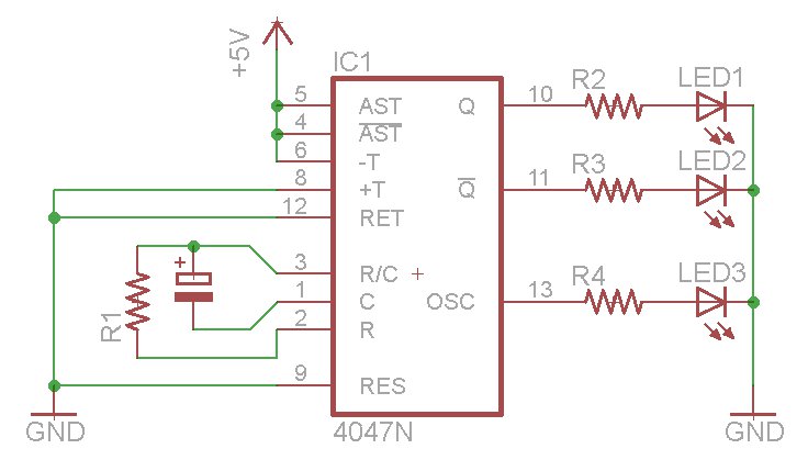
The oscillator output generates a signal that is approximately twice the frequency of Q. The other pins will be considered subsequently. In a brief video demonstration, LEDs are connected to all three outputs, illustrating the alternating behavior of Q...
This compact receiver is slightly larger than an AA battery. It is powered by two LR44 button cells, which are relatively costly and may not have a long lifespan. There is an intention to search for LR44 batteries at...
Derating is the method of reducing a device's operational limits as temperature increases, specifically concerning the device's power dissipation in relation to rising ambient temperature. Ambient temperature refers to the air temperature measured below a semiconductor device in an...
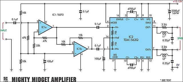
It is based on a Philips class-H audio amplifier integrated circuit and can deliver 36W RMS or 70W music power, all from a 13.8V supply. The new Mighty Midget Amplifier can produce approximately 36W RMS continuously into a 4-ohm...
The motor control circuit depicted in the image utilizes the LM339 comparator among other components. When the input control signal is high (PWL), comparators A and A3 activate the power amplifier circuit, which consists of A4, VT5, and VT6,...
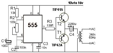
12V power inverter circuit utilizing a 555 timer for an electronic project. The 12V power inverter circuit is designed to convert a DC voltage of 12 volts into an AC voltage suitable for powering small electronic devices. The core component...