
Digital pressure measuring circuit
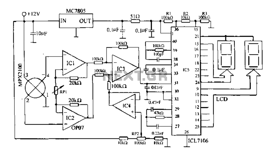
The AD7710/7715/7730 series of integrated circuits are designed for precise digital pressure measurement and signal conditioning applications. These multifunctional devices are equipped with a robust digital interface that facilitates communication with microcontrollers or other digital systems through a control port. The inclusion of a clock generator ensures that the internal operations of the ICs are synchronized, enabling accurate timing for data acquisition and processing.
The digital filter incorporated within these ICs plays a crucial role in minimizing noise and enhancing the signal quality before it undergoes further processing. This is particularly important in pressure measurement applications where ambient noise can significantly affect the readings. The amplitude modulation (A/modulation) feature allows for effective signal conditioning, ensuring that the output signal is optimized for subsequent analysis.
A programmable gain amplifier (PGA) is integrated into the circuit to allow for flexible signal amplification, accommodating a wide range of input signal levels. This feature is essential for applications that require precise measurement across varying pressure ranges. The analog-to-digital (A/D) converter converts the conditioned analog signal into a digital format, enabling easy integration with digital systems for further processing and display.
The internal function block diagram illustrates the various components and their interconnections within the IC, providing insight into the operational flow of the device. The pin functions are meticulously defined to facilitate proper connections in application circuits, ensuring that users can effectively utilize the device in their specific applications. The accompanying application circuit diagram serves as a practical guide for implementing the IC in real-world scenarios, showcasing typical configurations and component values necessary for optimal performance.
Overall, the AD7710/7715/7730 series offers a comprehensive solution for digital pressure measurement, combining advanced signal conditioning features with user-friendly interfacing capabilities, making it suitable for a wide range of industrial and commercial applications.Digital pressure measuring circuit AD7710/7715/7730 multifunction digital sensor signal conditioning ICs. They integrate a digital interface with the control port, a clock gene rator, a digital filter, A/modulation, programmable gain amplifier, A/D converter and other electric path. Their internal function block diagram, pin functions and the corresponding application circuit diagram in Fig.
Related Circuits
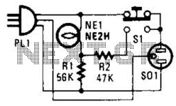
If residing in a cold climate, it is reassuring to confirm the functionality of an engine-block heater. This device indicates whether the heater is operational. To use, connect PL1 to a power outlet; the NE1 indicator should illuminate. Next,...
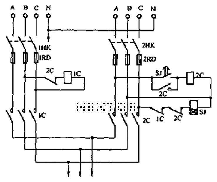
A dual three-phase power line circuit is illustrated in the figure. When the knife switches 1HK and 2HK are closed simultaneously, the normally closed contact 1C disconnects the power supply to the time relay SJ, allowing power to reach...
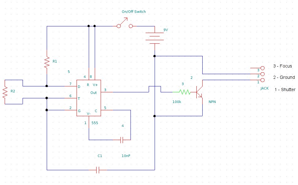
This document provides information on constructing a DIY time-lapse circuit that enables a camera to automatically capture images at specified time intervals. These images can then be compiled to create a time-lapse film. The circuit utilizes a 2.5 mm...

The circuit expands a single 15-pin D-sub VGA output to multiple outputs, allowing for the connection of up to six monitors simultaneously. The input VGA connector is positioned on the left side, while the six output VGA connectors are...
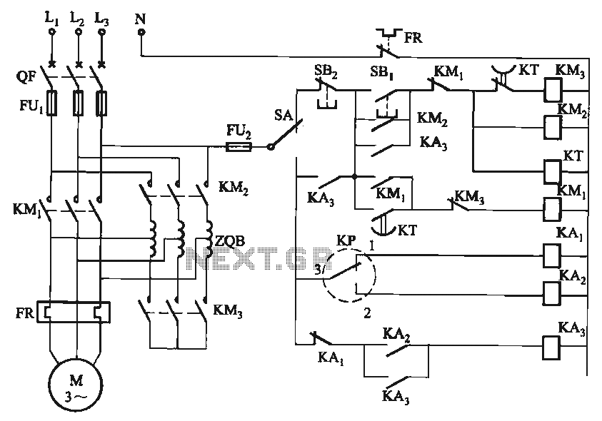
The circuit utilizes a motor auto-voltage transformer for starting. The motor auto-voltage transformer start circuit is designed to provide a controlled method for initiating the operation of an electric motor. This type of circuit is particularly beneficial in applications where...
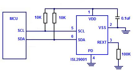
The Intersil ISL29001 is a digital light sensor designed to measure light intensity and easily interface with a microcontroller. The Intersil ISL29001 is a highly integrated digital light sensor that operates using a photodiode and an analog-to-digital converter (ADC) to...
Warning: include(partials/cookie-banner.php): Failed to open stream: Permission denied in /var/www/html/nextgr/view-circuit.php on line 713
Warning: include(): Failed opening 'partials/cookie-banner.php' for inclusion (include_path='.:/usr/share/php') in /var/www/html/nextgr/view-circuit.php on line 713