
Dual-phase power switchover circuit schematic

The dual three-phase power line circuit operates as a failover mechanism to ensure continuous power supply to a load in the event of outages in either of the two power sources (A or B). The circuit utilizes two knife switches (1HK and 2HK) to control the flow of electricity. When both switches are closed, the circuit allows current to flow to the load through the normally closed contact 1C. This configuration is designed to provide redundancy; if one power source fails, the system can automatically switch to the other source without manual intervention.
The time relay SJ plays a critical role in this circuit, providing a delay that prevents rapid cycling between power sources during transient outages. The adjustable time delay (0 to 60 seconds) allows for flexibility based on the specific application and load requirements. Once the time relay is activated after a power failure, it transitions from its normally open state to closed, energizing contactor 2C. This contactor is responsible for maintaining power to the load while disconnecting the failed power source.
The self-locking feature of contactor 2C ensures that once it is energized, it remains engaged even if the triggering signal from the time relay is removed. This is crucial for maintaining stability in the power supply to the load. The circuit is designed with safety in mind; the interruption of the power supply to contactor 1C ensures that it does not inadvertently attempt to reconnect to a failed source, thereby protecting the system from potential damage.
In summary, this dual three-phase power line circuit effectively manages power supply redundancy through the use of strategic contacts and a time relay, ensuring reliable and continuous operation of the load under varying conditions. Proper selection of contactors based on load size is essential for optimal performance and reliability of the system. As shown in Figure is a dual three-phase power line circuit from the vote. When electricity at the same time closing the knife switch 1HK and 2HK, 1C normally closed contacts d isconnect the power supply SJ time relay. Power to the load. When A power outage for any reason, 1C contactor release, then IC normally closed, power relay SJ time line on the graph, time delay relay after a few seconds, so SJ delay normally open closes, 2C was electrically energized and self-locking. Since the 2C pull its normally closed one hand off-delay line drawing power, on the other hand double break 1C coil power supply circuit, so that the power to stop power supply A, B power supply to ensure normal power supply.
After working for some time if the B power outage, 2C normally closed automatically switched line circle 1C A power supply replaced. Contactor shall choose according to load size; time relay available 0 ~ 60S AC relay.
Related Circuits
Temperature indicators and temperature-based products have garnered significant interest due to their numerous applications and various possible solutions, each presenting unique advantages and disadvantages. This concept focuses on a sensor interface that delivers high accuracy while minimizing board space....
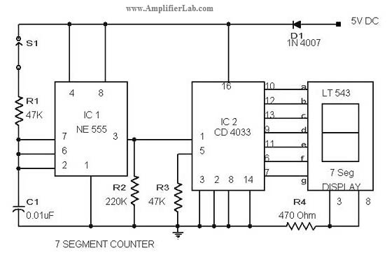
The circuit diagram of a 7-segment counter circuit has been published here. This circuit consists of the counter IC CD4033 as its central component. The 7-segment counter circuit utilizing the CD4033 integrated circuit (IC) is designed to display decimal digits...
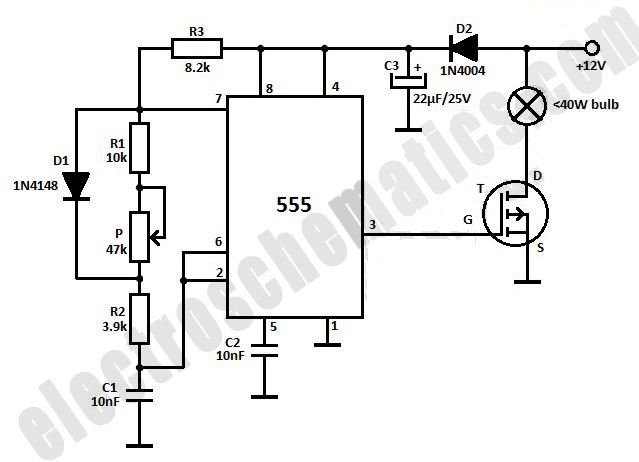
This light dimmer is designed to adjust the brightness of 12V light bulbs utilizing the widely recognized 555 timer, which is configured as an astable multivibrator. The pulses generated by the timer control the power delivered to the light...
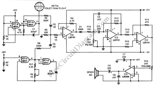
This schematic diagram illustrates a single-chip Theremin circuit. A Theremin is an electronic musical instrument that detects hand movements to control tones and frequency. The circuit employs two separate Colpitts LC oscillators to generate a beat frequency. The frequencies...
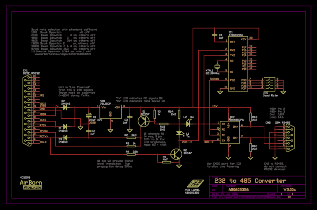
The new version of the RS485 interface addresses the issues associated with RTS control, which was a challenge in the previous design. However, implementing this solution requires a microprocessor, adding complexity to the design. This unit is currently being...
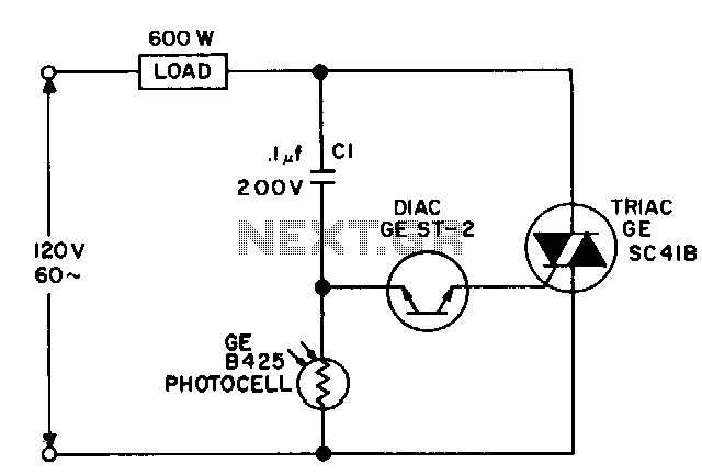
For a dark photocell with high resistance, the voltage across the diac rises rapidly in response to the line voltage due to the current flowing through capacitor C1, which triggers the diac early in the cycle. When the resistance...