
expand from one 15 pin d-sub VGA output to multiple others circuit

The circuit operates by utilizing a primary VGA input signal that is split into multiple output signals for the monitors. The VGA input is connected to the bases of the transistors, which act as switches for the output connections. When a signal is present at the VGA input, it activates the corresponding transistors, allowing the video signal to pass through to the output connectors. Each output connector is connected to a separate transistor configuration, ensuring that the signal integrity is maintained across all connected monitors.
The choice of using quad ECG2322 transistors is significant due to their ability to handle the required switching without introducing excessive noise or distortion to the signal. The transistors are configured in a manner that allows for efficient signal amplification and distribution. The circuit's design minimizes the load on the VGA source, which is crucial for maintaining the performance of the primary video output.
Powering the circuit from the PC power supply ensures that there is a stable 5-volt source available for the transistors to operate effectively. This design choice also contributes to the low power consumption of the circuit, making it suitable for applications where multiple displays are needed without overloading the graphics card or the power supply.
In summary, this VGA output expansion circuit is a practical solution for users requiring multiple monitor setups, providing flexibility and ease of use while ensuring efficient power management and signal integrity. The use of Orcad Capture 9.2 for schematic generation aids in visualizing and implementing the circuit design effectively.The circuit that allows you to expand from one 15 pin d-sub VGA output to multiple others. I built upon the schematic found online here and expanded it to allow up to 6 monitors connected at once! The input VGA connector is on the left while the 6 output VGA connectors are on the right side. The circuit is very simple though th ere are a ton of wires. It basically uses 5 transistors per output connector. The boxes in the middle are quad ECG2322 transistors so I needed a total of 8 to get the 6 monitors. The amazing thing about this circuit is that I could have kept going. You can hook up as many monitors as you want, I just limited myself to 6. The reason we can keep connecting is that the circuit draws very very little current (nearly zero) from the input source due to the input connecting to the base of the transistor. The base current near zero does not let current enter the right half of the circuit. Thus, the right half is powered by a 5 volt source which I stole from the PC power supply. Check out the original webpage for a more detailed explanation. I used Orcad Capture 9. 2 to generate the schematic. 🔗 External reference
Related Circuits
This simple amplifier is designed to add a headphone jack to equipment that does not have this feature. The Headphone Buffer circuit board is compact (1.2" x 1.4"), allowing it to fit into even the smallest spaces, and its...
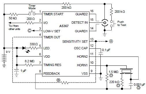
A simple ionization smoke detector with interconnect and timer alarm circuit can be constructed using the A5367 low-current, CMOS circuit, which provides all essential features for an ionization-type smoke detector. This CMOS IC, manufactured by Allegro MicroSystems, includes interconnect...
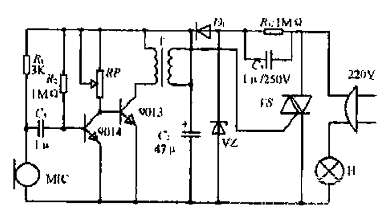
22W by Ct and R, RC Buck, rectified by n. c, filtering. vz 3V DC regulated output power, before U, V2 and MIC power supply. When the audio signal reaches the beam, the microphone MI converts acoustic energy into...
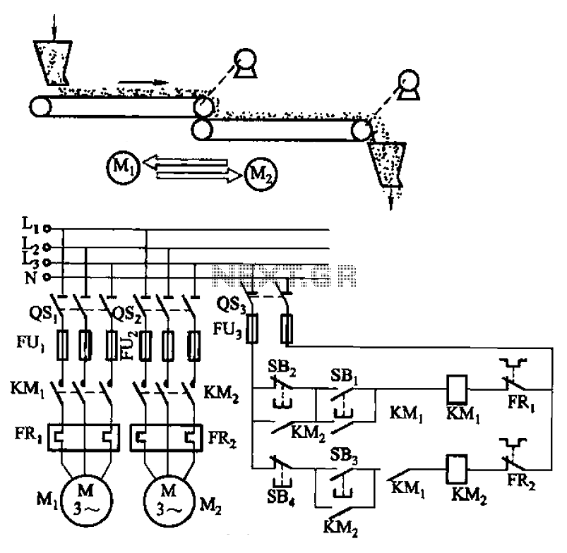
The circuit depicted in Figure 3-86 utilizes a line utilization time relay to control two motors, starting one before the other after an initial stall. The time relay KTi can be adjusted to modify the starting interval of the...
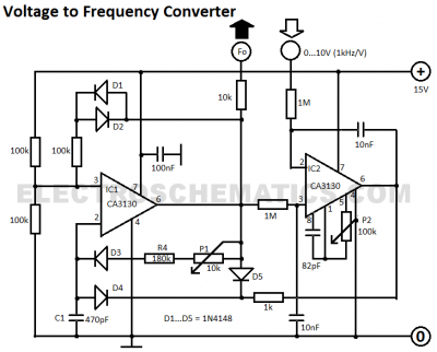
This voltage-to-frequency converter circuit features a voltage-controlled oscillator with a small deviation of 0.5%. The integrated circuit IC1 operates as a multivibrator. The voltage-to-frequency converter circuit is designed to convert an input voltage into a corresponding frequency output. The core...

The circuit consists of a 5V TOP414G isolated switching power supply with a 2A output. C1 serves as the input filter capacitor. The circuit includes a voltage clamp protection mechanism composed of VD1. The control terminal is connected to...