
digital remote thermometer
The circuit operates by utilizing a temperature sensor that generates a voltage output related to the ambient temperature. This output is fed into an analog-to-frequency converter within the transmitter section. The converter processes the voltage signal and generates a frequency output that is directly proportional to the temperature. This frequency modulated signal is then superimposed on the mains supply lines, allowing it to be transmitted over long distances without the need for additional communication lines.
At the receiving end, the circuit incorporates a frequency counter that monitors the bursts of frequency signals arriving from the mains supply. The counter is calibrated to decode the frequency back into a temperature reading. The decoded information is then displayed on three 7-segment LED displays, with the first two displays representing whole degrees and the last display representing tenths of a degree. This configuration allows for a clear and precise visual representation of the temperature.
The design ensures effective operation over distances of up to one hundred meters, which is particularly advantageous in large buildings or industrial environments where direct wiring between the sensor and display may not be feasible. The use of the mains supply for signal transmission minimizes the need for additional wiring and simplifies installation.
Power supply considerations are also crucial in this design. Both the transmitter and receiver sections are powered from the mains supply, ensuring that they remain operational without the need for batteries or external power sources. The circuit's sensitivity and accuracy can be further enhanced by utilizing high-quality components and proper calibration methods during installation. This temperature measurement system is ideal for applications requiring reliable and accurate temperature monitoring in a variety of environments.This circuit is intended for precision centigrade temperature measurement, with a transmitter section converting to frequency the sensor`s output voltage, which is proportional to the measured temperature. The output frequency bursts are conveyed into the mains supply cables. The receiver section counts the bursts coming from mains supply and shows the counting on three 7-segment LED displays.
The least significant digit displays tenths of degree and then a 00.0 to 99.9 °C range is obtained. Transmitter-receiver distance can reach hundred meters, provided both units are connected to the mains supply within the control of the same light-meter.. 🔗 External reference
Related Circuits

An FM and AM transmitter integrated into a compact device utilizing the CD4001 integrated circuit. It broadcasts at 20 MHz for AM and 100 MHz for FM. The described transmitter combines both Frequency Modulation (FM) and Amplitude Modulation (AM) capabilities...
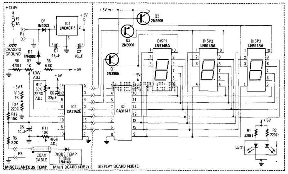
A diode (IN4148) is utilized as a temperature sensor. IC2 is an A/D converter with BCD output. A reference voltage set by R7 is applied to the positive input of IC2. As the temperature rises, the voltage across the...
%2Bwith%2Banimation%2Bsimulation%2Bcircuit.png)
The Johnson digital counter, also known as the Twisted Ring Counter, is a synchronous shift register that incorporates feedback from the inverted output (Q`) of the last flip-flop. The Q` output of the final flip-flop is connected back to...
This circuit measures the distance covered during a walk. The hardware is housed in a small box that can be slipped into a pants pocket, with the display designed as follows: the leftmost display D2 (the most significant digit)...
This circuit employs a digital voltmeter, consisting of IC1 and IC3, to indicate fuel quantity as a percentage of a full tank. It is designed to accommodate two types of fuel sensors: one with low resistance indicating a full...
.png)
Gratitude is extended for the manual that was purchased; it is as described, enabling the continuation of work on the TV. The service will be utilized for all future manual needs. Thank you once again. Best regards, Lazlo. Most...