
Digital Miscellaneous Temperature Gauge
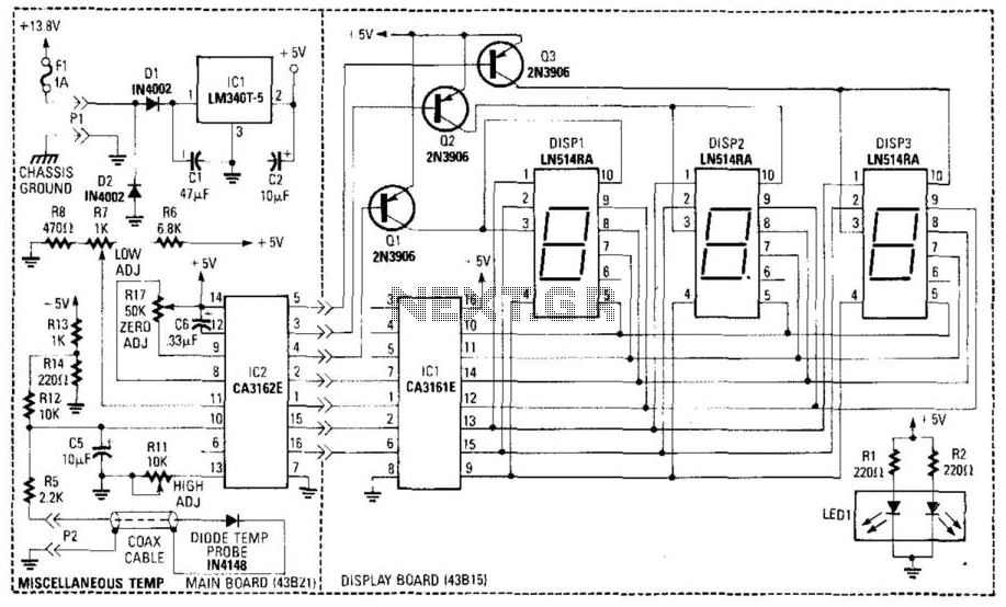
The circuit employs a diode, specifically the IN4148 model, as a temperature sensor due to its temperature-dependent forward voltage drop characteristics. As the temperature increases, the forward voltage drop across the diode decreases, leading to a change in the voltage across the sensor resistance. This change in voltage is critical for the operation of the A/D converter (IC2), which is configured to provide a Binary-Coded Decimal (BCD) output.
The reference voltage, established by resistor R7, is introduced to the positive input of IC2. This reference voltage serves as a baseline against which the voltage from the temperature sensor is compared. As the temperature rises, the decrease in the voltage across the diode sensor translates into an increased differential input voltage between pins 10 and 11 of IC2. This differential voltage is essential for accurate temperature readings and is directly related to the temperature being measured.
Resistor R3 is integrated into the circuit for low calibration adjustment, enabling fine-tuning of the lower end of the measurement range. This adjustment ensures that the output from the A/D converter accurately reflects the actual temperature at lower levels. Conversely, resistor R7 not only sets the reference voltage but also plays a crucial role in high calibration adjustment, allowing for precise scaling of the output.
R17 is included in the circuit to zero the A/D converter, ensuring that the output reads zero at a defined reference point, which is vital for accurate measurements. The combination of these components allows for a robust temperature sensing solution that can be calibrated for precision in various applications, making it suitable for environments where accurate temperature measurement is critical. A diode (IN4148) is used as a temperature sensor. IC2 is an A/D converter with BCD output. A refere nce voltage set by R7 is applied to the positive input of IC2. As the temperature increases, the voltage across the temperature sensor resistance decreases. This increases the differential input voltage across pins 10 and 11 of IC2. R3 adjusts low calibration. R17 zeros the A/D converter and R7 adjusts high calibration. 🔗 External reference
Related Circuits
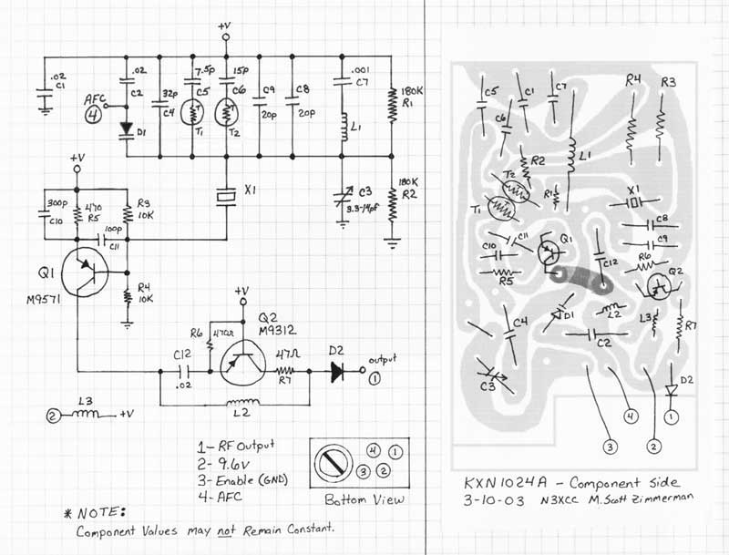
This document addresses the replacement of the crystal in various types of Temperature Compensated Crystal Oscillators (TCXOs), including Motorola "Channel Elements," GE "Integrated Circuit Oscillator Modules" (often referred to as ICOMs), and RCA TCXOs. The term "element" will be...
This Project is used to indicate the temperature and it is also used as controller. The system will get the temperature from the IC and it will display the temperature over the seven segment display and this temperature was...
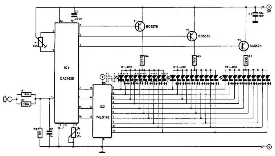
The voltage to be measured is digitized in an analog-to-digital (A/D) converter and then displayed in three decimal digits. The display consists of three groups of 10 LEDs. The meter can only be used for measuring direct voltages. The...
Temperature measurement and monitoring will be economical and straightforward if the TC9400 V/F converter is utilized with an appropriate voltage input. The TC9400 is a versatile voltage-to-frequency (V/F) converter that can be effectively employed in temperature measurement applications. By integrating...
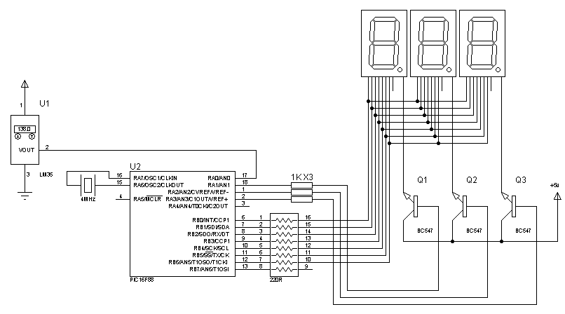
Assistance is needed to locate a schematic and code for a digital thermometer utilizing an LM35 temperature sensor and a 7-segment display, capable of measuring temperatures from 0 to 150.5 degrees Celsius. The required code must be included. The digital...
Unlike most surface-mounted device (SMD) resistors, SMD ceramic capacitors do not have their values marked. To determine the value of these capacitors, a capacitance meter is required. SMD ceramic capacitors are widely used in modern electronic circuits due to their...
Warning: include(partials/cookie-banner.php): Failed to open stream: Permission denied in /var/www/html/nextgr/view-circuit.php on line 713
Warning: include(): Failed opening 'partials/cookie-banner.php' for inclusion (include_path='.:/usr/share/php') in /var/www/html/nextgr/view-circuit.php on line 713