
Digital Step-Km Counter

The circuit operates on the principle of measuring the distance walked based on the number of steps taken, utilizing a mercury switch as a step counter. The mercury switch closes with each step, sending a pulse to the monostable multivibrator formed by IC1A and IC1B. This configuration helps to filter out noise and bouncing that could result from the mechanical action of the switch, providing a clean signal to the subsequent counting circuitry.
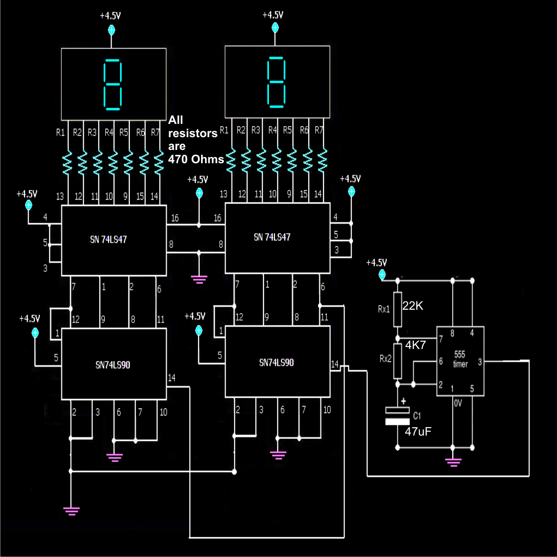
The pulse generated is then fed into IC2, a frequency divider that reduces the pulse frequency by a factor of 64. The output from IC2 is used to activate the display and sound the beeper, indicating the completion of distance milestones. The displays (D1 and D2) are driven by IC3 and IC4, which divide the pulse further to represent the distance in kilometers and hectometers accurately, while also managing the illumination of the decimal points for clarity.
Power management is an essential aspect of the design. The display only activates when needed, conserving battery life, which is critical for portable devices. The reset function is designed to prevent accidental clearing of the distance count, ensuring that users maintain accurate records of their walking sessions.
The audio feedback provided by the piezo sounder alerts the user to each completed distance segment, enhancing the usability of the device during physical activities. The ability to disable the sound is a thoughtful feature for users who may prefer a silent operation.
Overall, the design is straightforward yet effective, providing a practical solution for distance measurement during walking or jogging activities, while ensuring ease of use and reliability through careful electronic design choices.This circuit measures the distance covered during a walk. Hardware is located in a small box slipped in pants` pocket and the display is conceived in the following manner: the leftmost display D2 (the most significant digit) shows 0 to 9 Km. and its dot is always on to separate Km. from hm. The rightmost display D1 (the least significant digit) sh ows hundreds meters and its dot lights after every 50 meters of walking. A beeper (excludable), signals each count unit, which occurs every two steps. A normal step is calculated to span approx. 78 centimeters, thus the LED signaling 50 meters lights after 64 steps or 32 mercury switch`s operations, the display indicates 100 meters after 128 steps and so on. For low battery consumption the display lights only on request, pushing P2. Accidental reset of the counters is avoided because to reset the circuit both pushbuttons must be operated together.
Obviously this is not a precision meter, but its approximation`s degree was found good for this kind of device. In any case, the most critical thing to do is placement and sloping degree of the mercury switch inside the box.
IC1A & IC1B form a monostable multivibrator providing some degree of freedom from excessive bouncing of the mercury switch. Therefore a clean square pulse enters IC2 that divide by 64. Q2 lights the dot of D1 every 32 pulses counted by IC2. IC3 & IC4 divide by 10 each and drive the displays. P1 resets the counters and P2 enables the displays. IC1C generates an audio frequency square wave that is enabled for a short time at each monostable count.
Q1 drives the piezo sounder and SW2 let you disable the beep. This circuit is primarily intended for walking purposes. For jogging, further great care must be used with mercury switch placement to avoid undesired counts. 🔗 External reference
Related Circuits
A simple frequency counter circuit can be easily constructed by any electronics enthusiast for its intended purpose. The circuit diagram was provided by Mr. Kapital through an order on Fiverr. The functioning of the circuit involves generating positive voltage...
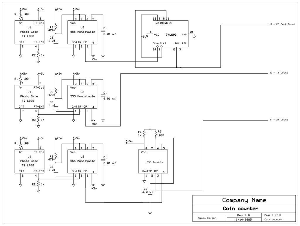
The next counter section operates similarly but is designed to count four quarters, single $1 coins (loonies), and single $2 coins (toonies). The circuit for the toonies is configured. The circuit for the counter section includes a digital counting mechanism...

The AD9835 combines the Numerical Controlled Oscillator (NCO), COS Look-Up Table, Frequency and Phase Modulators, and a Digital-to-Analog Converter on a single integrated circuit. With more easy words you can say that this circuit is an oscillator where the...
The DD-2 is a highly regarded digital delay pedal that emulates an analog sound. It was initially sold from 1983 until it was discontinued in 1986, after which it was relaunched without any modifications as the DD-3 (noting that...
A signal conditioner for a pH meter probe requires high input impedance. The signal conditioning of the pH meter probe is achieved by incorporating a buffer. The design of a signal conditioner for a pH meter probe is critical for...

This is a CMOS-compatible (and ideally also TTL-compatible) input that includes over-voltage and under-voltage protection. Schmitt triggers are utilized to accommodate inputs with long transition times. It has been verified to function at frequencies up to 30 MHz. The described...