
Digital Sound Recorder With Avr And Dataflash

The Z86E02 microcontroller is designed to facilitate the development of various electronic applications due to its versatile features and compact architecture. The integrated 512-byte EPROM provides sufficient memory for storing program instructions, while the 61 bytes of RAM allow for temporary data storage during operation. The 14 I/O ports enable the microcontroller to interact with external components, making it suitable for controlling devices such as dimmer switches.
In dimmer switch applications, the Z86E02 can be programmed to adjust the brightness of lighting fixtures by varying the power delivered to the load. The use of a Watch-Dog Timer ensures that the system remains operational by resetting the microcontroller in case of a software failure. The Power-On Reset feature guarantees that the microcontroller initializes correctly when power is applied, preventing erratic behavior.
The Low-Voltage Protection circuit is essential for ensuring reliable operation, particularly in environments where voltage levels may fluctuate. The RC Oscillator option provides a simple means of generating clock signals, which can be adjusted by changing the resistor and capacitor values, allowing for flexibility in timing applications. The register architecture facilitates efficient data handling and manipulation, while the two Analog Comparators can be utilized for monitoring voltage levels, enhancing the microcontroller's capability in dimming applications.
In implementing a dimmer switch using the Z86E02, a two-pole design is necessary to manage the AC power phase control effectively. The microcontroller can be programmed to analyze the input from the user interface (such as a potentiometer or toggle switch) and adjust the output accordingly to control the TRIAC or other switching devices that regulate the power to the lighting load. This intelligent control mechanism not only provides a smooth dimming experience but also increases energy efficiency and extends the lifespan of the lighting components.
In summary, the Z86E02 microcontroller's combination of memory, processing capabilities, and integrated features makes it an excellent choice for developing modern dimmer switches, aligning with current consumer preferences for more advanced lighting control solutions.One of ZiLOG`s most popular Z8 One Time Programmables (OTPs), the Z86E02 features a 512-byte EPROM 61 bytes of RAM, 14 I/Os, Watch-Dog Timer Power- On-Reset, a Low-Voltage Protection circuit and one additional Timer Special fea- tures on the Z86E02 include an RC Oscillator option, Register architecture, and two Analog Comparators All these feature s make the Z86E02 suitable for many types of applications, including dimmer switches. There seems to be a consumer trend in overhead lighting systems toward dim- mer-controlled wall switches. Simple on/off switches are almost a thing of the past. Dimmers, however, must use an electrical two-pole design, as opposed to the standard electrical four-pole power phase control.
This application note describes the basic implementation of an intelligent and cost-effective dimmer using ZiLOG Z86E02. 🔗 External reference
Related Circuits
SPI stands for Serial Peripheral Interface, which is the simplest among all communication protocols. Eight-bit data registers in the devices are connected by wires. These data registers function as shift registers, with one device controlling the data exchange within...
This is a simple 3-digit digital voltmeter. A PIC16F676 microcontroller is utilized to read analog signals (voltage) and display the value on a 3-digit 7-segment display. Similar principles can be applied to measure DC current using a parallel resistor...
To create a dashboard digital voltmeter circuit diagram that includes a parts list, PCB layout, and component placement, a full PDF article is available for download. The dashboard digital voltmeter circuit is designed to provide an accurate measurement of voltage...

This circuit generates the sound of two canaries singing in a cage. Two LM324 quad amplifiers constitute seven oscillators. One oscillator serves as an on/off control, while the remaining six produce the sounds of two canaries. A 9-V supply...
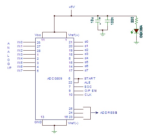
Analog to digital converter modules are utilized in microcontroller-based projects where analog signals need to be transformed into digital signals for further processing in a microcontroller. The integrated chip employed for this purpose is the ADC 0809. This post...
The Digital Thermometer 0-100 °C is a device designed for temperature measurement in Celsius. It utilizes a microcontroller AT89C4051 as its data processor. The temperature sensor employed in this thermometer is the LM35D, which provides accurate temperature readings. The...