
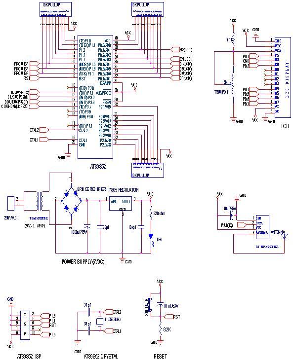
Schematic Diagram of Dashboard Digital Voltmeter

The dashboard digital voltmeter circuit is designed to provide an accurate measurement of voltage levels and display them on a digital interface. The primary components of the circuit typically include a microcontroller, an analog-to-digital converter (ADC), a display module (such as a 7-segment display or an LCD), resistors, capacitors, and a voltage reference.
The microcontroller serves as the central processing unit, interpreting the voltage readings from the ADC and controlling the display output. The ADC converts the analog voltage signal into a digital format that the microcontroller can process. It is crucial to select an ADC with sufficient resolution to ensure accurate voltage readings.
The display module is responsible for visually presenting the measured voltage. Depending on the complexity of the design, the display can be configured to show additional information such as battery status or voltage range. The choice of display technology (LED, LCD, etc.) will depend on the desired visibility and power consumption requirements.
The PCB layout is essential for ensuring that the components are arranged efficiently and that signal integrity is maintained. Proper placement of components can minimize noise and interference, which is particularly important in sensitive measurement applications. The PCB should also include appropriate traces for power distribution and signal routing.
In addition to the schematic diagram, a comprehensive parts list should be provided, detailing each component's specifications, such as resistance values, capacitance, and power ratings. This list aids in sourcing components and ensures compatibility within the circuit.
Overall, the design of a dashboard digital voltmeter circuit requires careful consideration of component selection, layout design, and functionality to achieve a reliable and accurate measurement tool.If you want to to try to make a Dashboard Digital Voltmeter Circuit Diagram including part lists, the PCB building and the placement of the components, you may download the article in full pdf here 🔗 External reference
Related Circuits
A milliamp meter can function as a voltmeter by incorporating a series resistance. The required resistance is calculated by dividing the full-scale voltage reading by the full-scale current of the meter movement. For instance, using a 1 milliamp meter...
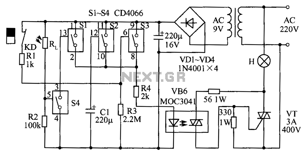
The circuit diagram illustrates a group of four analog electronic circuit switches (S1 to S4). Switches S1, S2, and S3 are utilized in a parallel delay circuit. When the power is activated, resistor R4 drives the triac VT, which...
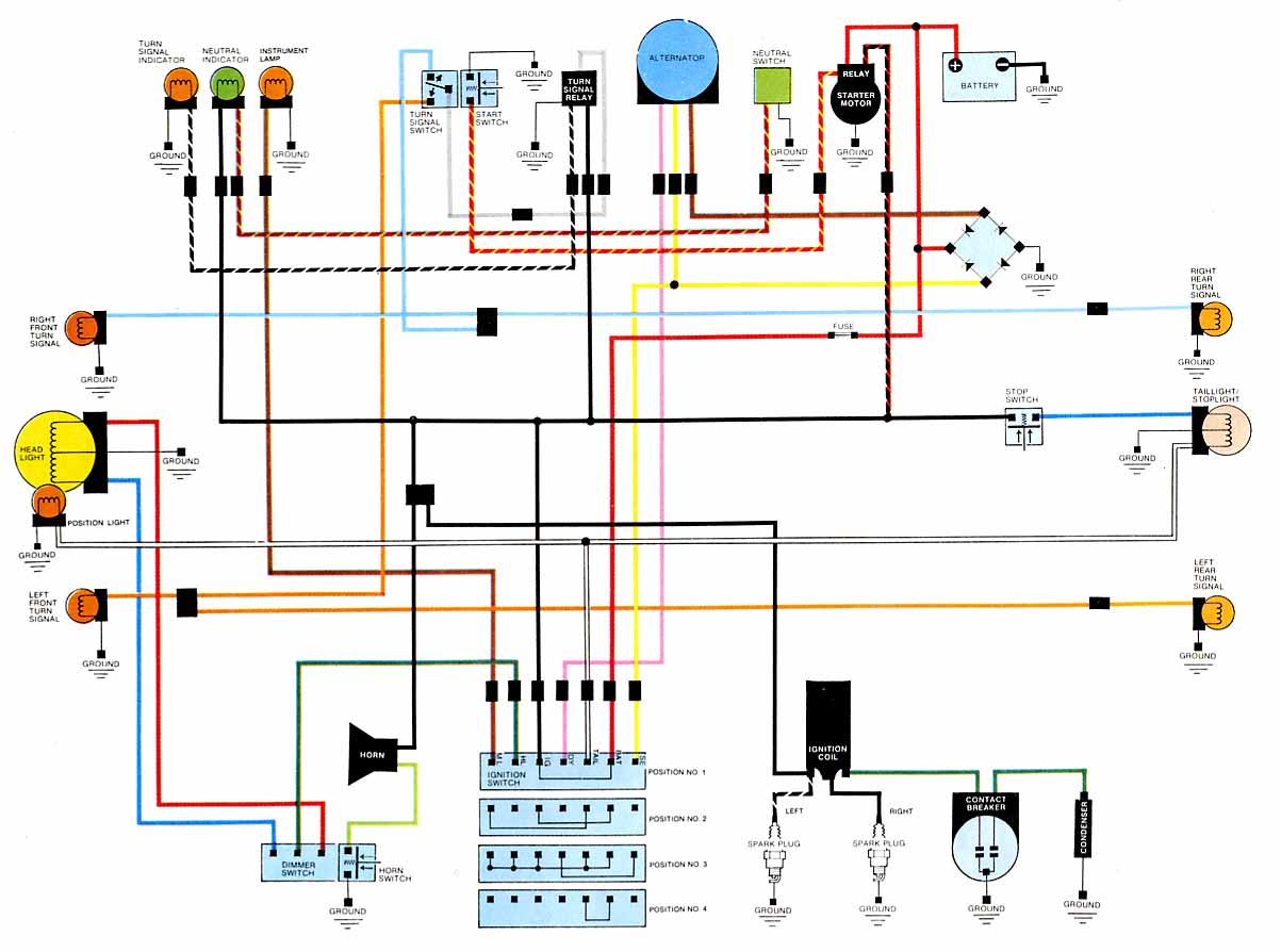
2012 Honda Odyssey Radio Wiring Diagram Manual PDF Download. The 2012 Honda Odyssey Radio Wiring Diagram Manual provides a detailed schematic of the audio system's wiring configuration for the vehicle. This manual is essential for understanding the connections and functionalities...
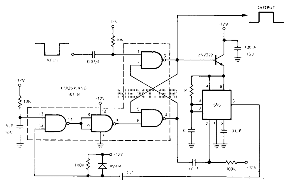
The 555 Timer facilitates a low-loss single-shot circuit and interfaces with the CMOS4011B NAND gate circuit. The standby power consumption is less than 50 µA. When the one-shot circuit is activated, the current consumption is 4.5 mA, and the...
RF Wireless Data Transfer communication circuit diagram. A wireless communication interface was implemented to facilitate data transfer from one point to another using RF technology. The RF Wireless Data Transfer communication circuit utilizes radio frequency (RF) technology to establish a...
Building a serial voltage meter to measure from 0 to 5 volts DC is straightforward. Utilizing MeLabs PicBasic and Microsoft Visual Basic Version 5 Pro is essential, as the MSComm control required for communication is not available in the Visual...