
Digital Stop Watch and Digital Timer Circuit

The digital stopwatch circuit utilizes the LM555 timer IC configured in astable mode to generate a continuous clock pulse. The frequency of this pulse can be adjusted by varying the resistor and capacitor values connected to the timer. This clock pulse serves as the timing reference for the circuit, enabling it to count time intervals accurately.
The MM74C926 is a 4-digit counter IC that counts the pulses generated by the LM555 timer. It is designed to handle binary-coded decimal (BCD) counting, allowing it to display numbers from 0 to 9999. The output from the MM74C926 is connected to a multiplexed 7-segment LED display, which visually represents the counted time.
The multiplexing technique is employed to reduce the number of required pins and to simplify the circuit design. Each segment of the display is controlled by a common control line, which is switched rapidly to create the illusion of a steady display. The circuit includes additional components such as resistors and capacitors to ensure the proper functioning of the timer and counter ICs.
In summary, this digital stopwatch circuit effectively combines the LM555 timer and the MM74C926 counter to provide a user-friendly timing solution, displaying elapsed time on a multiplexed 7-segment LED display.A digital stop watch or digital timer circuit schematic built around timer IC LM555 and 4-digit counter IC MM74C926 with multiplexed 7-segment LED display.. 🔗 External reference
Related Circuits
This controller is designed primarily for controlling model trains and can deliver approximately 12-15 Volts, though it operates effectively at voltages as low as 3V, including a 6V supply for certain accessories. The maximum output current is theoretically around...
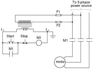
The most challenging aspect of interpreting ladder diagrams, particularly for individuals familiar with electronic schematic diagrams, is the representation of electromechanical relays. The operation of a motor control circuit should be explained, detailing what occurs when the "Run" switch...
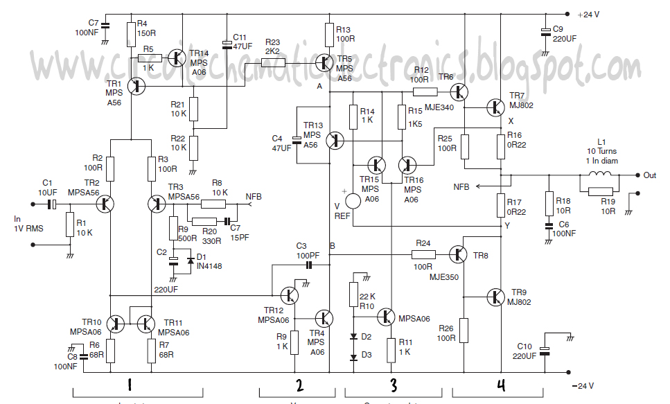
This design schematic represents a Class A power amplifier. It closely matches the operating parameters of Class B to facilitate comparison, particularly with a negative feedback (NFB) factor of 30dB at 20 kHz. The front end is similar to...
This LED flasher circuit is a classic two-transistor flip-flop. It is a popular circuit often built by beginners in electronic circuit design. The schematic diagram of this well-known LED flasher circuit consists of two transistors, two capacitors, four resistors,...
1. A robot may not injure a human being or, through inaction, allow a human being to come to harm. 2. A robot must obey the orders given to it by human beings, except where such orders would conflict...
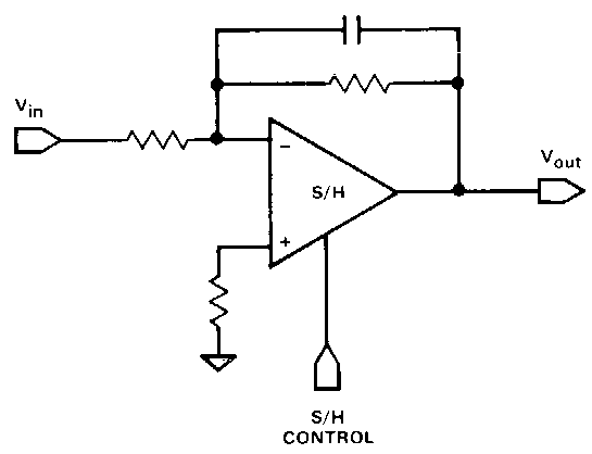
Circuit 1kZ incorporates an operational amplifier (op-amp) component with two inputs, one output, and up and down ports, typically utilized for power supply rails. Additionally, there is a buffer component, which is likely provided by TikZ itself rather than...