
circuit schematic symbol for buffer with control input
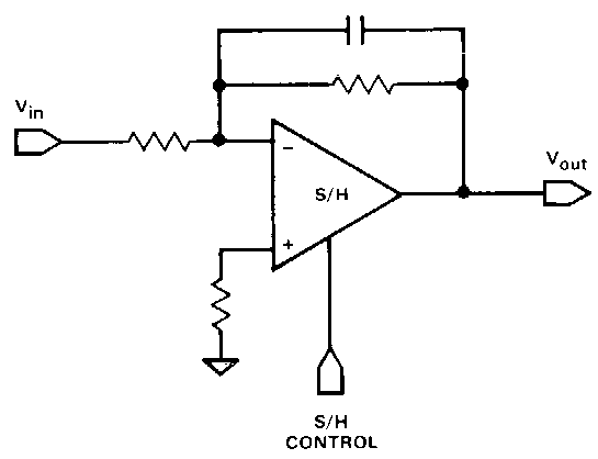
The circuit described employs an operational amplifier (op-amp) as the central component, which is essential in various analog signal processing applications. The op-amp configuration includes two inputs (inverting and non-inverting), allowing for differential signal amplification. The output port facilitates the delivery of the amplified signal, while the up and down ports are typically connected to power supply rails, ensuring the op-amp operates within its specified voltage range.
In conjunction with the op-amp, a buffer stage is introduced into the design. This buffer component serves to isolate the input signal from the output, preventing loading effects that could distort the signal integrity. The buffer is characterized by a single input and output, with the absence of vertical ports indicating a straightforward implementation. However, the requirement for vertical ports is noted, which would typically be utilized for control signals in various applications.
The application of a track-and-hold amplifier necessitates specific design considerations, as it captures and holds the instantaneous value of an analog signal for a defined period. The design of a one-input track-and-hold amplifier symbol aims to encapsulate the necessary functionality while minimizing visual complexity. This approach is beneficial in high-level block diagrams, where clarity and simplicity are paramount. The envisioned symbol would abstract the internal workings of the amplifier, allowing for easier interpretation and integration into larger circuit designs.
Tri-state buffers are another relevant component in this context, commonly used in digital circuits to control the flow of data. These buffers can be enabled or disabled, allowing for multiple outputs to share a common bus without interference. The inclusion of control inputs in the design of these buffers further enhances their versatility in various applications.
Overall, the circuit design emphasizes the importance of operational amplifiers and buffer stages in analog signal processing, while also considering the need for control mechanisms in more complex configurations. This comprehensive approach ensures that the schematic effectively communicates the intended functionality while maintaining a high level of clarity for the user.circuit 1kz has an op amp component type with two inputs, output, and up and down ports, usually used for power supply rails. There`s also a buffer component type (which I think is provided by tikz itself, not the circuitikz library) which has one input and one output and no vertical ports.
I`m looking for a buffer/amp with one input, one output, a nd the vertical ports, for use as control pins. My use case is a track-and-hold (aka sample-and-hold) amplifier symbol, but a tri-state buffers are also very common and require a control input. Ok, that figure uses a two-input SHA. But I`m sure you can imagine what the one-input version should look like (basically, I`m trying to make a single symbol that hides all that complexity, for a high-level block diagram).
🔗 External reference
Related Circuits
The schematic for an infrared burglar alarm circuit is depicted in Figure 1. The infrared transmitter operates as a multivibrator with an oscillation frequency of 40 kHz, utilizing the NE555 integrated circuit (IC2), along with resistors R1 and R2...
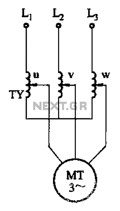
The circuit depicted in Figure 3-176 illustrates an adjustment method that allows the motor to operate at equilibrium. The adjustment range is relatively wide; however, it necessitates a three-phase voltage regulator, which incurs higher input costs. The circuit design in...
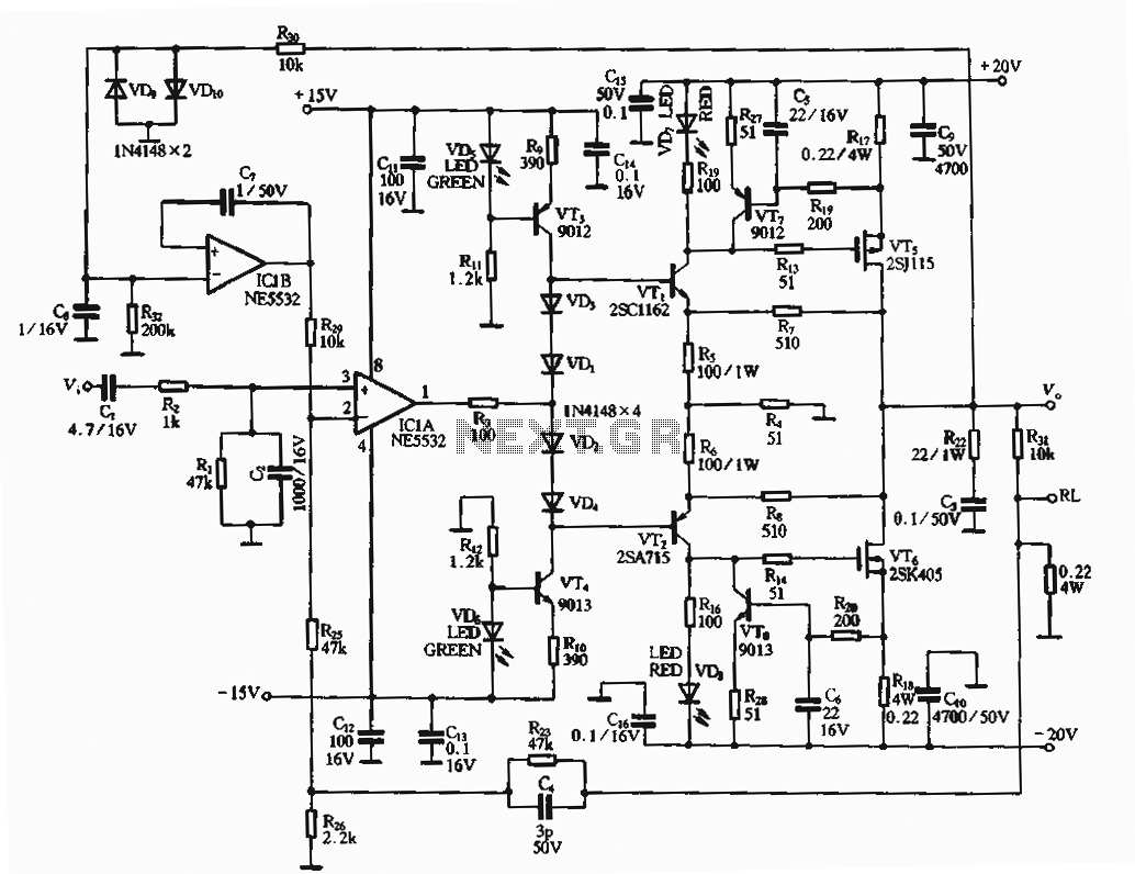
The circuit utilizes an FET amplifier configuration for output, incorporating an NE5532 operational amplifier powered by a 15V supply. The output stage features a FET that amplifies the voltage after passing through several stages. The bias circuit for the...
The circuit consists of two 555 timer oscillators configured in a dual timer arrangement, both set up in astable mode. Components include a 1N4148 diode and a 555 integrated circuit. The dual 555 timer circuit operates in astable mode, generating...
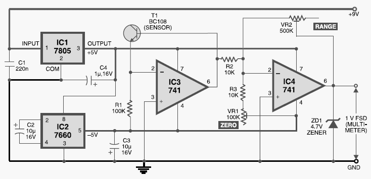
This digital thermometer circuit diagram uses a common 1N4148 diode as the temperature sensor. The temperature coefficient of the diode is -2 mV/°C. The digital thermometer circuit leverages the characteristics of the 1N4148 diode, which has a well-defined temperature coefficient....
The intercom schematic provides a reliable communication line and is straightforward to construct. The circuit consists of an amplifier, two switches, and two loudspeakers. If additional stations (speakers) are desired, more switches can be incorporated into the circuit. The...
Warning: include(partials/cookie-banner.php): Failed to open stream: Permission denied in /var/www/html/nextgr/view-circuit.php on line 713
Warning: include(): Failed opening 'partials/cookie-banner.php' for inclusion (include_path='.:/usr/share/php') in /var/www/html/nextgr/view-circuit.php on line 713