
Digital temperature measuring
The described system employs a thermocouple, specifically a Ni-NiCr type, which is known for its reliability and wide temperature range. The thermocouple generates a small voltage that varies with temperature, following the Seebeck effect. This voltage is then fed into a voltage-to-frequency converter (VFC), which is a critical component that translates the voltage signal into a frequency output.
The VFC operates by adjusting its conversion ratio, which is essential for ensuring that the frequency output is directly proportional to the temperature being measured. This linear relationship allows for straightforward interpretation of the frequency reading as a temperature value. For example, a frequency output of 350 Hz indicates a temperature of 350°C, making it easy to read and understand.
The digital frequency meter is connected to the output of the VFC, which captures the frequency signal and displays it in a user-friendly manner. This setup is particularly advantageous for applications requiring precise temperature monitoring and control, such as in industrial processes or laboratory environments.
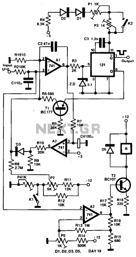
The thermocouple's operational range of 5°C to 800°C, with a specified accuracy of ±1°C, makes this measuring system suitable for a variety of applications, including material testing, furnace temperature monitoring, and other high-temperature environments. The design of the system ensures that it can provide reliable and accurate temperature readings over its operational range, facilitating effective temperature management in various settings.The output voltage of a thermocouple is converted into frequency measured by a digital frequency meter. The output thermocouple signal is proportional to the temperature difference between the hot junction and the thermostat kept at 0°C, it drives the voltage-to-frequency converter changing the analogue input signal into the output frequency with the conversion ratio adjusted in such a way, that the frequency is equal to the measured temperature in Celsius degrees, e.g., for 350°C the frequency value is 350 Hz.
The measuring set connected with Ni-NiCr thermocouple permits you to measure the temperatures within the range of 5°C - 800°C with ±1°C error. 🔗 External reference
Related Circuits
This circuit controls a load, specifically a DC brushless fan, based on a temperature comparison with a setpoint. The transducer utilized is a diode in the forward bias configuration. When forward biased, the forward voltage drop across the diode...
This circuit is a low-cost frequency meter that operates within the range of 1 Hz to 1 MHz. It utilizes an IC1 Schmitt trigger to regulate the input signal, adjusting it to a suitable level for IC2, IC3, and...
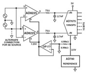
The Common Mode Rejection Ratio (CMRR) facilitates the rejection of high-frequency common-mode voltages, leading to the attenuation of elevated ambient noise levels from utility lines, industrial machinery, and other sources of radiation. The circuit diagram presented illustrates the advantages...
This electronic clock comprises the LM8365 and the LDD640R displays. The LM8365 can show the hour/minute and month/day. Users can set two alarm outputs, AD1 and AD2, by pressing either the 12h or 24h button. The operating voltage range...
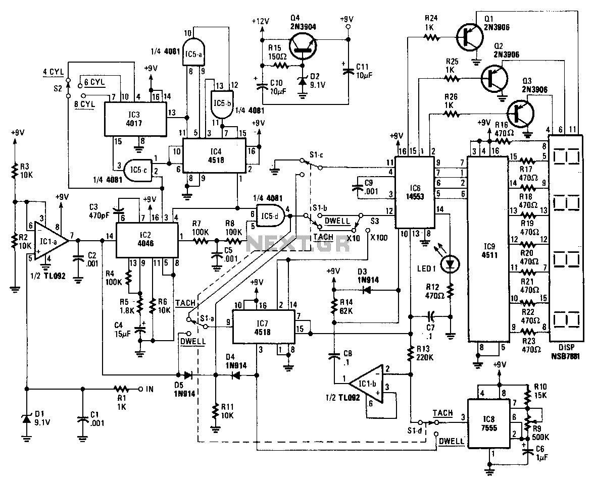
The core component of the circuit is ICZ, a 4046 micropower phase-locked loop (PLL). The incoming signals are processed through a buffer, IC1a, and its associated components before being fed into the PLL. The frequency of the incoming signal...
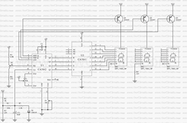
The circuit measures the car water temperature. CA3161 is a counter and 7segment driver to display amount of temperature on 7segments. The temperature sensor is a diode, 1N4148. This is set near of the Car Radiator. To obtain the...