
1MHZ Digital Frequency Meter
This frequency meter circuit is designed for versatility and ease of use, making it suitable for various applications in electronics. The integration of a Schmitt trigger (IC1) ensures that the input signal is clean and stable, which is crucial for accurate frequency measurement. The use of multiple displays (DIS1, DIS2, DIS3) allows for clear visual representation of the frequency being measured, with the capability to indicate when the measurement exceeds a predefined limit through the decimal point functionality.
The timer section, utilizing IC5A and IC5B, provides flexibility in measurement intervals, allowing users to select between 1 second and 1 millisecond interruptions based on their specific needs. This feature enhances the circuit's adaptability for different measurement scenarios, whether quick bursts of frequency or longer monitoring periods are required.
The calibration process is straightforward, requiring a precision frequency meter or signal generator, which emphasizes the importance of maintaining accuracy in frequency measurements. The circuit's design also accounts for potential signal interference, with the placement of Q1-IC1 being a critical factor in reducing noise from high-frequency signals, ensuring reliable operation.
Overall, this frequency meter circuit is an efficient and effective tool for measuring frequencies across a broad range, suitable for both hobbyists and professionals in the field of electronics. Its low-cost design, combined with its functional features, makes it a valuable addition to any electronic toolkit.This circuit is a frequency meter, low cost. It covers region 1HZ until 1MHZ. The IC1 schmitt trigger that it regulates the signal of entry and him changes in reasonable level suitable for the IC2-3-4. With the tenth pulse in the entry of IC2/1, is produced a pulse `` carry `` in the IC3/5. The same moment the IC2 causes the depiction in the DIS1, show [0], the IC3 causes the DIS2, to show [ 1 ]. When in the entry of IC3 it reaches and the tenth pulse, the DIS2 show [ 0 ] and the DIS3 show [ 1 ], (with total depiction 100, having the display in right order). The exit `` carry`` off IC4/5, can be used in order to it turns on the decimal point (comma) the DIS1, in order to it shows a situation over the limits of measurement.
The timed begins with the one of half double timer (IC5A). Switch S1 select the interruption the time in 1sec or in 1ms. At the duration of this interruption, second half the (IC5B), it produces a interruption of depiction 2 or 3sec. , at the duration which counter cut off by the entry and the displays remain OFF. In the end of depiction, a pulse RESET, begins the interruption of time/depiction. The critical point is round the Q1-IC1, which should be placed as long as it becomes more near in the jack of entry, to reject of parasitic signals of high frequency.
For the regulation, we can use a frequency meter good precision (if you do not have you are lented) and a generator of signal. We put switch S1, in place [HZ], we apply in the entry a low frequency and we regulate the trimmer TR2, so that we take the right clue, which should suit with source frequency meter.
We repeat also the regulation for the department of KHZ, with a higher frequency. The supply of circuit becomes with a battery +9V, if it is used as portable or from suitable power supply if it is incorporated in some unit that exists already. 🔗 External reference
Related Circuits
This circuit incorporates a datasheet-compliant trigger signal, reversed polarity protection, an optional test button, and the capability for battery operation. It utilizes either the U1 L601E3 or MAC97A8 triac, rated for 400 V and 1 A. When U1 is...
This is a transmitter circuit that can transmit both FM and AM signals simultaneously at two different frequencies: FM at 100 MHz and AM at 20 MHz. The described transmitter circuit is designed to operate at two distinct frequency...
This document outlines the construction of a compact frequency counter utilizing an inexpensive PIC microcontroller and several seven-segment LED displays. A PIC programmer necessary for programming the PIC 16F628 is accessible on DL4YHF's website. Requests for programmed PICs or...
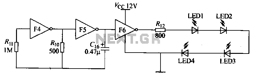
Gates F4, F5, and F6 together form a low-frequency oscillator that drives high-brightness light-emitting diode (LED) flashes. The light-emitting diodes may be arranged around the booth seat for decorative purposes. The automatic referral machine is used prior to operation...
This project is currently under construction and has not been validated for functionality. A signal generator, resistor, and oscilloscope were utilized to measure the value of an inductor for a battery charger project. In the search for an affordable...

Phase noise is a critical performance parameter of frequency synthesizers for wireless applications. RF system designers of phase-modulated cellular systems, such as PHS, GSM, and IS-54, require low noise local oscillator (L.O.) or frequency synthesizer blocks. This document describes...