
Digital Voltmeter of your Own

The voltmeter circuit operates by utilizing the LM3914 as the main display driver. This IC is designed to drive either a bar or dot display and can indicate voltage levels through its 10 outputs. The input voltage is fed into the LM3914, which compares it against its internal reference voltages. The reference voltages are set to divide the maximum input voltage (in this case, 9V) into ten equal segments, each representing a 1V increment.
The LM3914 outputs a high signal on the pin corresponding to the range of the input voltage. For instance, if the input voltage is 5V, the LM3914 will activate the fifth output pin, illuminating the corresponding segment on the display.
To convert the output of the LM3914 into a binary value, the circuit incorporates the 74147 priority encoder. This IC takes the active output from the LM3914 and encodes it into a binary format, which can then be processed for display. The binary output is then sent to the 7447 seven-segment display driver, which converts the binary input into a format suitable for driving a common anode seven-segment display.
The 7447 ensures that the correct segments of the display are illuminated based on the binary input, allowing for a clear numerical representation of the measured voltage. The design ensures that the voltmeter is simple yet effective, providing a visual indication of voltage levels without the complexity of a multimeter.
It is important to note that while this circuit can provide a straightforward means of measuring DC voltages, its sensitivity is capped at 1V, meaning that it may not be suitable for applications requiring higher precision or measurement of voltages outside the specified range. Proper calibration and reference voltage settings are crucial for ensuring accurate readings within the specified limits.How to build a voltmeter for DC voltage measurements without using multimeter testing This is a simple digital voltmeter circuit that can measure voltages from 0V to 9V. The main part of this circuit is a dot bar display driver IC LM3914. Input voltage applied to this IC generates an output which is converted into a binary value by the priority en
coder IC 74147. It is then displayed on the seven segment display by the help of a common anode seven segment display driver IC 7447. However the voltmeter accuracy of this digital voltmeter schematic is limited to a sensitivity of 1V.
IC LM 3914 is a bar dot display driver which has 10 output pins (1 to 10). This IC has 10 comparators with a reference voltage each (1/10 to 10/10 of reference voltage) 🔗 External reference
Related Circuits
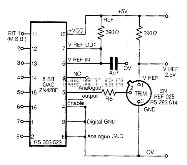
This circuit demonstrates a straightforward approach to achieving a voltage reference that can be adjusted using an 8-bit Digital-to-Analog Converter (DAC) equipped with an integrated voltage reference. The analog output from the DAC controls the trim pin of the...
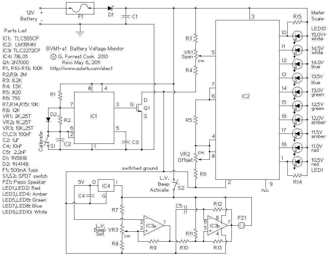
This is a low power voltmeter circuit that can be used with alternative energy systems that run on 12 and 24 volt batteries. The voltmeter is an expanded scale type that indicates small voltage steps over the 10 to...
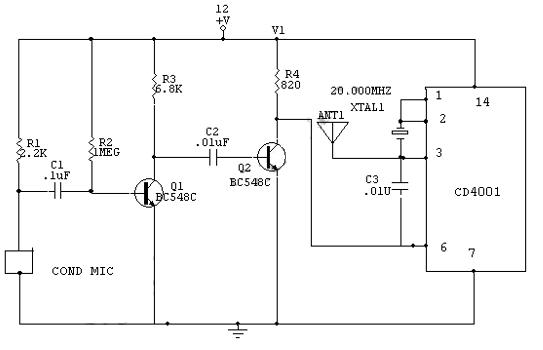
This is a transmitter circuit that can transmit both FM and AM signals simultaneously at two different frequencies: FM at 100 MHz and AM at 20 MHz. The described transmitter circuit is designed to operate at two distinct frequency...
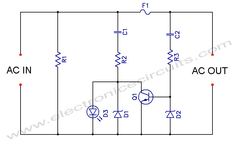
LED Blown AC Fuse Indicator Circuit Diagram. This circuit monitors an AC fuse. In this circuit, the LED indicator shows whether or not the fuse is blown. The LED Blown AC Fuse Indicator Circuit is designed to provide a visual...
The DD-2 is a highly regarded digital delay pedal that emulates an analog sound. It was initially sold from 1983 until it was discontinued in 1986, after which it was relaunched without any modifications as the DD-3 (noting that...
This circuit employs a digital voltmeter, consisting of IC1 and IC3, to indicate fuel quantity as a percentage of a full tank. It is designed to accommodate two types of fuel sensors: one with low resistance indicating a full...