
LED Voltmeter
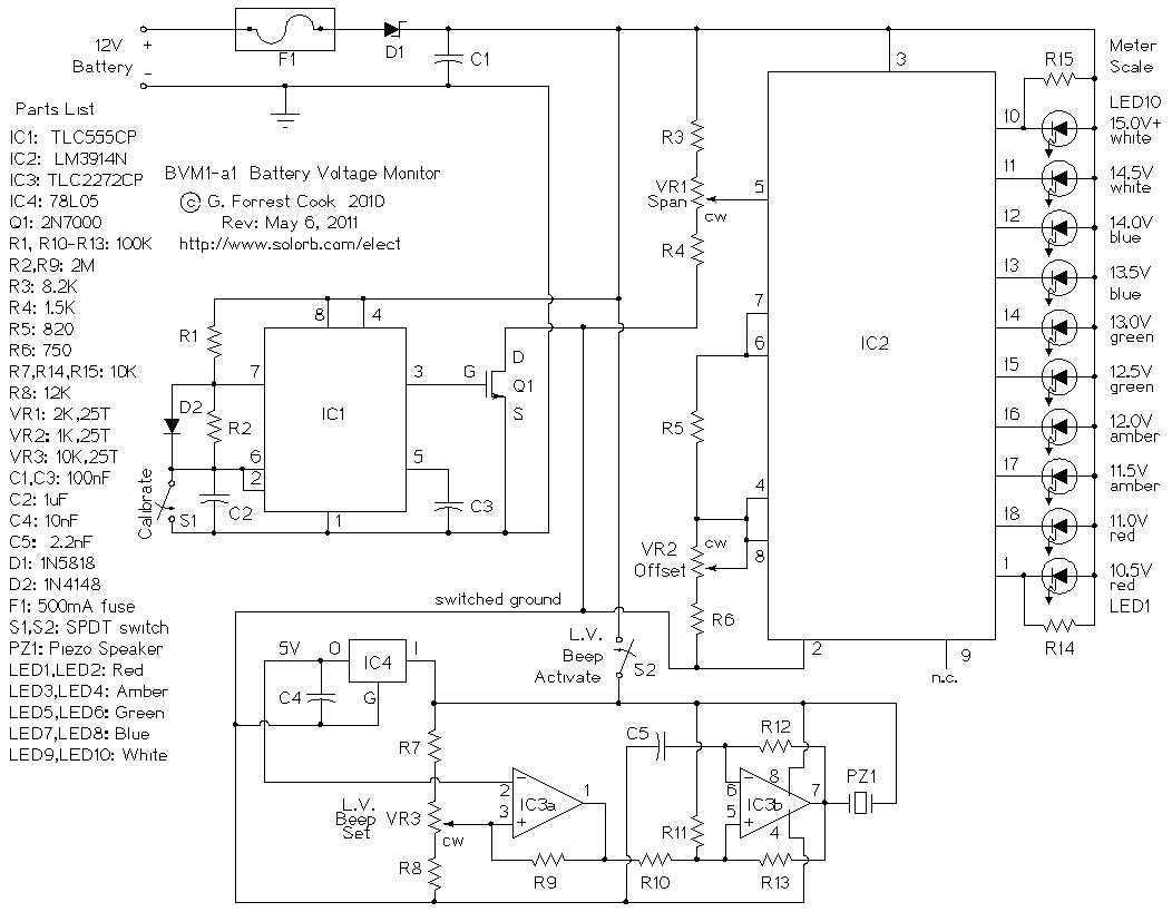
The low power voltmeter circuit is designed specifically for monitoring battery voltages in alternative energy systems, such as solar or wind power setups. The circuit utilizes an expanded scale voltmeter configuration, which allows for precise measurements of small voltage changes within the specified ranges. For 12V systems, the voltmeter can accurately display voltages from 10 to 16 volts, while for 24V systems, it covers the range of 22 to 32 volts.
The circuit's design emphasizes energy efficiency, with a power consumption of only 14 milliwatts at 12 volts and 160 milliwatts at 24 volts. This low power requirement is particularly advantageous in renewable energy applications, where battery longevity is crucial. The voltmeter employs a low duty-cycle blinking mode, wherein the LED indicators illuminate only momentarily, thus reducing overall power usage. This blinking occurs in a repeating cycle of 2 seconds, allowing for periodic voltage readings without significant energy expenditure.
The voltmeter can be calibrated to display equal voltage steps across different voltage ranges, making it versatile for various applications. This feature enables users to customize the display according to their specific monitoring needs, ensuring that critical voltage levels are easily readable. The circuit typically consists of a voltage divider network, an analog-to-digital converter (ADC), and a microcontroller or dedicated display driver to manage the LED indicators and provide the necessary visual feedback.
In summary, the low power voltmeter circuit is an efficient and adaptable solution for monitoring battery voltages in alternative energy systems, featuring precise measurement capabilities, low power consumption, and customizable display options.This is a low power voltmeter circuit that can be used with alternative energy systems that run on 12 and 24 volt batteries. The voltmeter is an expanded scale type that indicates small voltage steps over the 10 to 16 volt range for 12 volt batteries and over the 22 to 32 volt range for 24 volt batteries.
Power consumption can be as low as 14mw when operated from 12V and 160mw when operated from 24V. It is possible to set the meter to read equal steps across a variety of upper and lower voltages. The meter saves power by operating in a low duty-cycle blinking mode where the LED indicators are only on and consuming power briefly during a repeating 2 se 🔗 External reference
Related Circuits
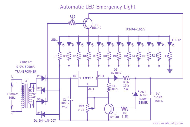
This is a cost-effective and straightforward emergency light circuit developed for CircuitsToday. It is an automatic emergency lamp with daylight sensing capabilities, meaning it detects darkness and turns on automatically, while also sensing daylight to turn off. The circuit...
This post discusses blue and white LED drivers utilizing a joule thief circuit. Further exploration of the circuit's functionality is provided, along with simulation points. The joule thief circuit is a simple and efficient boost converter that allows for the...
The project involves using a 555 timer in conjunction with a 4029 counter and a 4511 decoder. The goal is to connect the outputs of the 4511 to a bar graph LED display, specifically to the "a-g" pins. The...
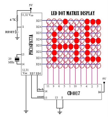
Multiplexed displays are electronic displays where the entire display is not driven simultaneously. Instead, sub-units of the display—typically rows or columns for a dot matrix display or individual characters for a character-oriented display—are multiplexed. This means that they are...
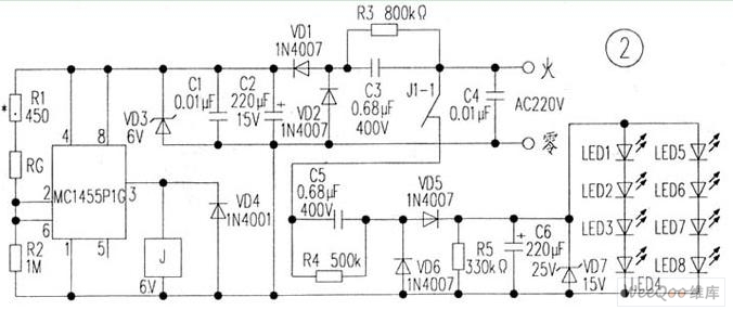
The circuit is depicted in Figure 1, while the electrical schematic diagram is presented in Figure 2. The AC voltage of 220V is reduced by components C3 and R3. The diodes VD1 and VD2 rectify the voltage, and capacitors...
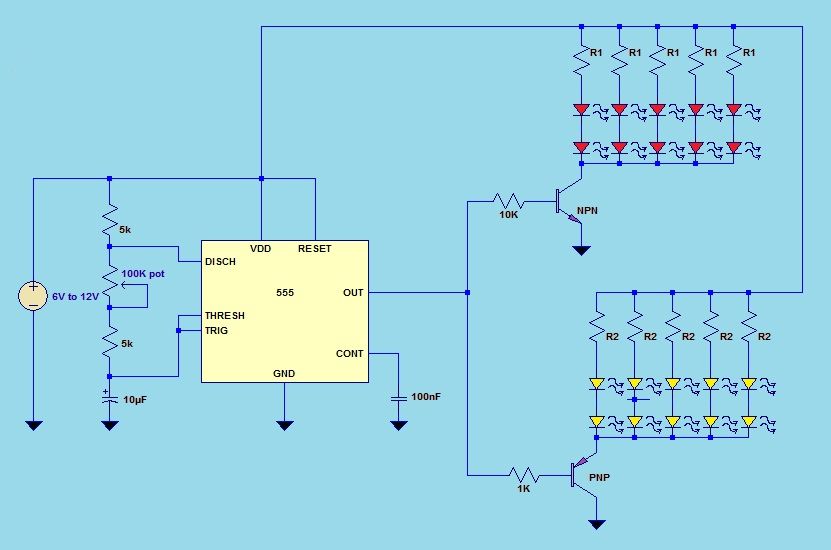
This project utilizes a 555 timer integrated circuit (IC) in an 8-pin configuration to control multiple LEDs. It is designed for quick assembly and allows for the adjustment of timing functions. The circuit employs a 555 timer in astable mode,...