
LED Blown AC Fuse Indicator

The LED Blown AC Fuse Indicator Circuit is designed to provide a visual indication of the status of an AC fuse. The primary component of this circuit is an LED, which illuminates when the fuse is intact and turns off when the fuse is blown.
The circuit typically includes a resistor in series with the LED to limit the current flowing through it, preventing damage to the LED. The fuse itself is connected in series with the AC supply. When the fuse is functional, current flows through the circuit, allowing the LED to light up.
In the event of a blown fuse, the circuit is interrupted, causing the LED to turn off. This provides a simple yet effective method for monitoring the status of the fuse without the need for complex circuitry.
To enhance reliability, the circuit may also include a diode in parallel with the fuse to provide a discharge path for any transient voltages that may occur when the fuse blows. This reduces the risk of damage to the LED and other components in the circuit.
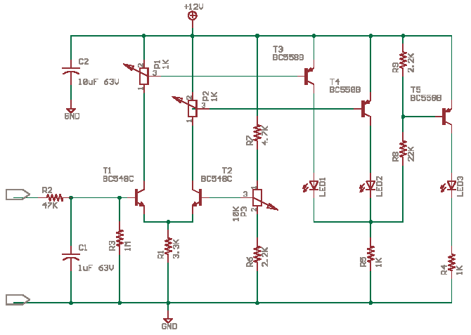
Overall, this LED Blown AC Fuse Indicator Circuit is a practical solution for quick visual checks on fuse integrity in various applications, ensuring that users are promptly alerted to any issues with the AC supply.LED Blown AC Fuse Indicator Circuit Diagram This circuit monitors a AC fuse. In this circuit, the LED indicator shows whether or not the fuse is.. 🔗 External reference
Related Circuits

A 1971 Lincoln Continental 4-door is experiencing a complete power failure inside the vehicle, particularly affecting the ignition switch. The battery cables, post connectors, and fusible link have been checked and are functioning correctly. All fuses in the fuse...
Various techniques demonstrate how enhanced PWM (pulse-width modulation) intensity control can be utilized in LED (light-emitting diode) drivers. PWM intensity control is a widely adopted method in LED driver circuits to regulate brightness levels. This technique involves modulating the width...
The circuit possesses significant educational value. It has not been tested. Users can simulate and test it or construct it to evaluate its performance. The circuit functions as a simple analog-to-digital converter. Optocouplers can be used in place of...

This simple and easy to make circuit is a 5 LED VU Meter based on LB1409 IC from SANYO, which will indicates the volume level of the audio signal it senses. SUPPLY 12V DC @ 50mA. PR1 REF SET....

The circuit utilizes a motor auto-voltage transformer for starting. The motor auto-voltage transformer start circuit is designed to provide a controlled method for initiating the operation of an electric motor. This type of circuit is particularly beneficial in applications where...

The ISL97676 can be utilized as an LED driver capable of managing six channels of LED current for TFT displays. This driver supports the operation of up to 78 LEDs with a voltage range of 4.5V to 26V, or...