
Digitally Controlled High Frequency VGA
Variable-gain amplifiers (VGAs) are integral components in various electronic systems, particularly in radio receivers where they play a critical role in managing signal levels. VGAs are designed to adjust the gain of an input signal dynamically, allowing for optimal signal processing under varying conditions. This adaptability is essential in applications where the amplitude of incoming signals can fluctuate significantly, ensuring that the output remains within the desired range for further processing.
In a typical radio receiver system, the VGA is positioned after the antenna and front-end filter stages. The input signal, which may vary in strength due to distance from the transmission source or interference, is fed into the VGA. The gain of the amplifier can be controlled either manually or automatically, depending on the design of the receiver. Automatic gain control (AGC) circuits are often employed to adjust the gain in real-time, ensuring consistent output levels regardless of input variations.
The VGA can be implemented using various technologies, including analog and digital methods. Analog VGAs utilize variable resistors or transistors to change gain, while digital VGAs may use digital potentiometers or programmable gain amplifiers controlled by microcontrollers. The choice of technology impacts the performance characteristics, such as linearity, bandwidth, and noise figure, which are critical in maintaining signal integrity.
Careful consideration must be given to the design parameters of the VGA, including input and output impedance, frequency response, and distortion characteristics. These factors influence the overall performance of the radio receiver, affecting sensitivity, selectivity, and signal-to-noise ratio. By optimizing these parameters, VGAs can significantly enhance the performance of communication systems, enabling clearer and more reliable signal reception.Variable-gain amplifiers (VGAs) can be used in may types of systems, such as radio receivers. In this system, the input signal voltage depends on an. 🔗 External reference
Related Circuits
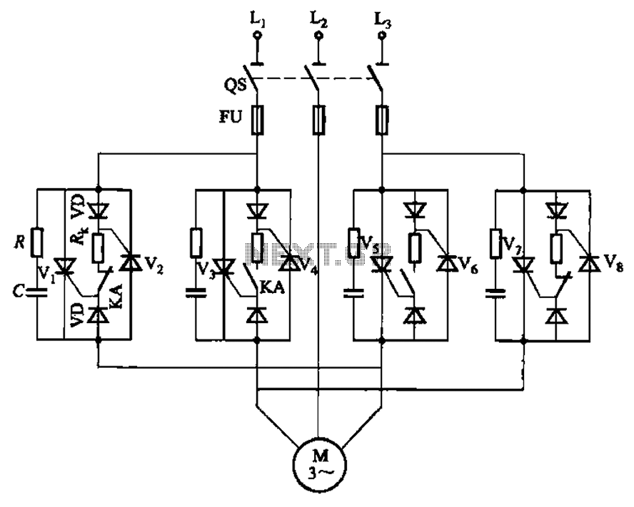
The circuit depicted in Figure 3-69 is designed for applications requiring frequent timing control for motor reversing operations. In this configuration, thyristors V1, V2, V7, and V5 are utilized for positive control of rotation, while thyristors V3, V4, and...
This is a 0 - 6 MHz DDS VFO controlled by a PIC16F84 (or C84). The VFO is separated into two modules, the DDS module and the controller module. The PCB layout (double sided) for the DDS module is...
Originally posted by Pano: "Like putting milk and sugar in your coffee. Next time by, your Turkish coffee comes with no sugar, Dave." The provided text appears to be an informal comment comparing the addition of sugar and milk to...
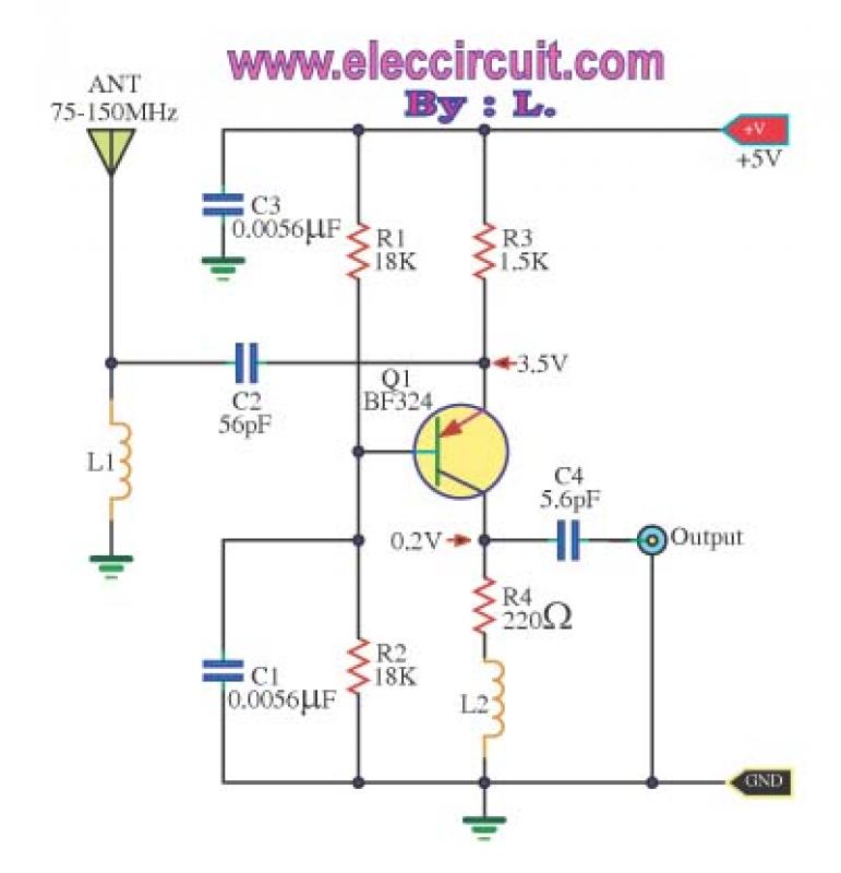
This is a wideband high-frequency amplifier circuit designed for a frequency range between 75-150 MHz. It utilizes a PNP transistor amplifier to enhance signal strength before it reaches the receiver of devices such as phones, FM radios, or amateur...
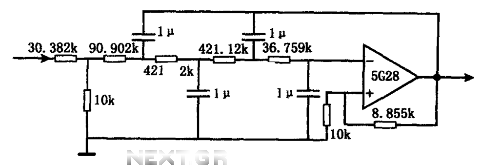
The circuit illustrated in the figure represents a staggered low-frequency active filter. This is a fourth-order Butterworth low-pass active filter designed to filter very low frequency (VLF) random pulse noise voltage at the DC level. The cut-off frequency is...
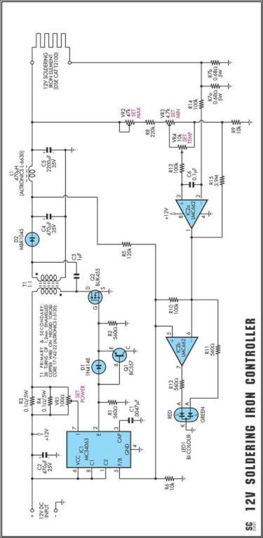
One reason why commercial soldering stations are expensive is that they typically require soldering irons with built-in temperature sensors. Commercial soldering stations are designed to provide precise temperature control and consistency during soldering operations, which is essential for achieving reliable...