
Wide band high frequency amplifier circuit
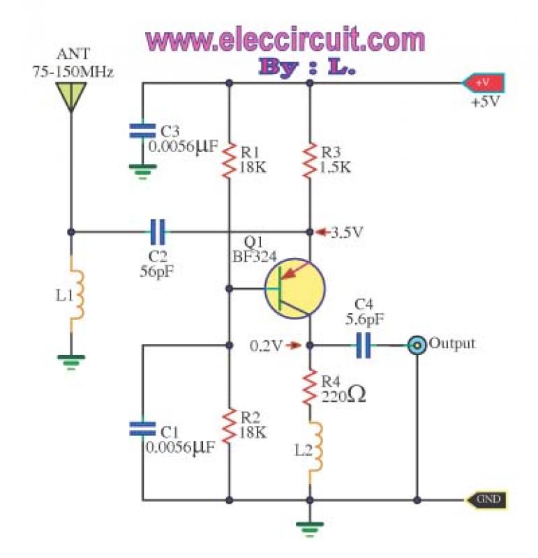
More: The L1 coil consists of 10 turns of 24 SWG enamel-coated magnet wire with an inside diameter of 3 mm, while the L2 coil has 13 turns of the same wire gauge with an inside diameter of 5 mm. Both coils are air-core types. The power supply for this circuit is +5 V, and it operates at a current of 2.5 mA. When selecting components, it is important to consider the antenna and the design of high-frequency printed circuit boards. The circuit can be assembled onto a universal PCB board, but care should be taken to minimize interference. A basic antenna and reasonable PCB design for high frequency are recommended. The component list includes resistors: R1 and R2 at 18K, R3 at 1.5K, and R4 at 220 ohms. Capacitors include C1 and C3 at 0.0056uF 50V, C2 at 56pF 50V, and C4 at 5.6pF 50V. The semiconductor used is Q1, which is a BF324 PNP transistor.
In this circuit design, the choice of components and their specifications is crucial for optimal performance. The resistors should be rated at ¼ W with a tolerance of +5%. The capacitors must be rated for at least 50V to ensure they can handle the voltage levels in the circuit. The inductive coils, L1 and L2, are integral to the amplifier's functionality, as they help in tuning the circuit to the desired frequency range while providing the necessary impedance matching.
The layout of the printed circuit board (PCB) should be carefully planned to minimize parasitic capacitance and inductance, which can adversely affect the performance of high-frequency circuits. It is advisable to use short traces and proper grounding techniques to reduce noise and improve signal integrity. Additionally, the assembly process should include a thorough inspection to ensure that all components are correctly oriented and soldered to avoid operational issues.
Overall, this wideband high-frequency amplifier circuit is suitable for applications requiring enhanced signal strength in the VHF range, making it an effective solution for various radio communication devices.This is Wide band high frequency amplifier circuit,Wide frequency band between 75-150 MHz,Using transistors, a PNP amplifier.To enhance the signal strength.Before the receiver of the phone. Or FM radio or amateur radio. If high-frequency signals, in particular, its VHF. The booster circuit is one, serves to amplify the signal strength only. Operation of the circuit. High-frequency range VHF, inductive antenna, to the emitter pin of the transistor Q1. so circuit held, in conjunction with the bass, a nice low output impedance. You can use a special access code 50 ohms, the antenna on the circuit at all.Signal at the Q1 will be expanded to increase.And sent to a tuner or receiver to the receiver.
The L1 coil wire enamel No. 24 SWG, thousands of rounds of 10, inside diameter 3 mm. And the coil L2 wire number. Thousands of 13 turns, diameter 5 mm. Stent both as a non-core, or an air core. The power supply is +5 V, this circuit while current is 2.5 mA. If the components to use. Should be based on the antenna. And design of high frequency printed circuit boards as well. How to assemble circuits The assembling circuit onto the universal PCB board as Figure 2 May have problems, the interference inserted come in, If assembly circuit to actually use. Should have a basic antenna and PCB design in high frequency reasonable. The components list Resistors size ¼ W +5% R1, R2__________18K R3_____________1.5K R4_____________220 ohm Capacitors C1, C3__________0.0056uF 50V C2_____________56pF 50V C4_____________5.6pF 50V Semiconductor Q1___________BF324___PNP Transistors Others L1___is 10 turns of 24 SWG enamel coated magnet wire wound with a inside diameter of about 3mm.
no core. L2____is 13 turns of 24 SWG enamel coated magnet wire wound with a inside diameter of about 5 mm. no core. 🔗 External reference
Related Circuits
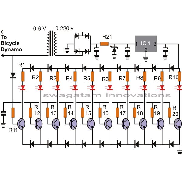
The article presents a circuit that can be used for indicating the riding speed of a bicycle. The bicycle speedometer circuit explained here utilizes standard components such as transistors and LEDs to effectively display a clear 10-step, accurately calibrated...
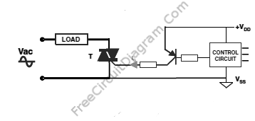
The output current of the control circuit must be amplified when the gate current needed to trigger the device exceeds the output current of the control circuit. To achieve the amplification of the control circuit output current, a suitable transistor...
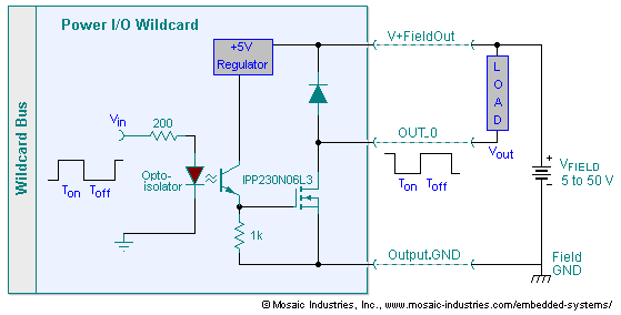
The embedded I/O board offers isolated high voltage switch inputs and eight high current, high voltage DC outputs. It utilizes optically isolated, open drain N-MOSFET transistors functioning as solid state relays (SSR) to control various resistive or inductive loads....

A very high-power amplifier with 10 pairs of power transistors. It can utilize MJ15024 and MJ15025 or MJ21193 and MJ21194. These 20 transistors function as the final active components. The design is based on four integrated circuits: TL072, TL074,...
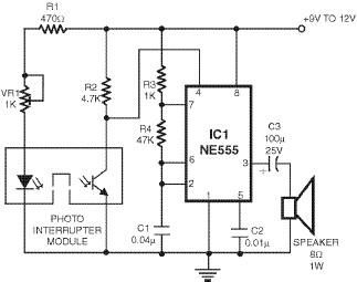
This smoke detector utilizes a 555 timer circuit along with common electronic components. The photo interrupter module serves as the smoke detection element, while the 555 timer is configured in astable mode to function as an audio frequency oscillator,...
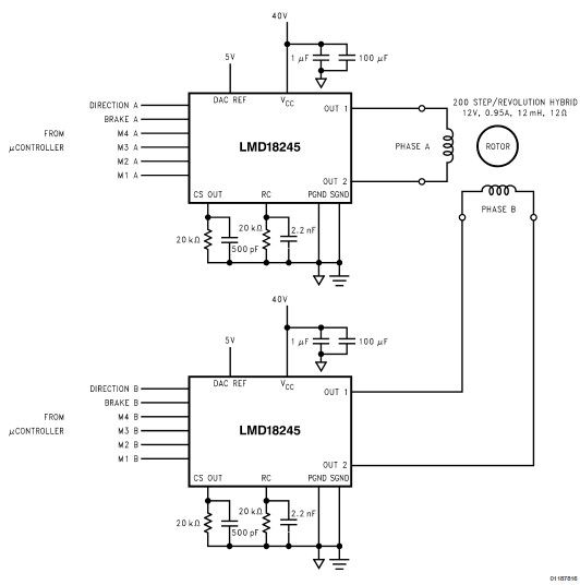
LMD18245 bipolar stepper motor driver circuit design using few electronic parts The LMD18245 is a versatile bipolar stepper motor driver designed to control stepper motors with precision and efficiency. This circuit utilizes a minimal number of electronic components, making it...
Warning: include(partials/cookie-banner.php): Failed to open stream: Permission denied in /var/www/html/nextgr/view-circuit.php on line 713
Warning: include(): Failed opening 'partials/cookie-banner.php' for inclusion (include_path='.:/usr/share/php') in /var/www/html/nextgr/view-circuit.php on line 713