
Dimming Control Circuit for LEDs
Warning: Undefined array key "extension" in /var/www/html/nextgr/view-circuit.php on line 468
Deprecated: strtolower(): Passing null to parameter #1 ($string) of type string is deprecated in /var/www/html/nextgr/view-circuit.php on line 468

A dimming control circuit for light-emitting diodes (LEDs) is designed to enhance the user experience by providing smooth brightness transitions while minimizing noise disturbances. The circuit operates by generating a dimming control signal characterized by alternating bright and dark phases. Each bright phase begins with an adaptive rising portion that allows the brightness of the LED to increase gradually from zero, avoiding abrupt changes that can lead to noticeable flickering or noise.
The architecture of the LED drive circuit typically incorporates a boost-type switching voltage regulator, which is essential for converting a lower input voltage into a higher output voltage required to drive one or more series-connected LEDs. The switching control circuit plays a critical role by generating a fixed-duty pulse drive signal that controls a switching transistor. The duty cycle of this signal is pivotal, as it directly influences the output voltage and, consequently, the current flowing through the LEDs. The relationship between the diode current and the output voltage can be expressed mathematically, allowing for precise control over the brightness levels.
In terms of human perception, the circuit leverages the fact that the human eye can average brightness over cycles of approximately 60 Hz, making it possible to create a visually appealing lighting effect without perceptible flicker. During the bright phase, the switching transistor is actively turned on and off in response to the pulse drive signal, while during the dark phase, the signal is blocked, keeping the transistor off. This method allows for control over the average brightness by adjusting the ratio of the bright to dark phases.
However, a challenge arises with this approach: the current noise peaks generated at the onset of each bright phase can be disruptive, particularly if the frequency of the bright-dark cycles falls within the audible range. To address this issue, the dimming control circuit is engineered to reduce these noise peaks, thereby enhancing the overall performance and user satisfaction.
In summary, the described dimming control circuit not only effectively manages the brightness of LEDs through adaptive control techniques but also incorporates design considerations to mitigate unwanted noise, resulting in a more refined and user-friendly lighting solution.A dimming control circuit generates a dimming control signal for determining brightness of at least one light-emitting diode. The dimming control signal has a plurality of bright-dark cycles, each of which consists of a bright phase and a dark phase.
The bright phase starts with an adaptive rising portion. The adaptive rising portion restricts the brightness of the at least one light-emitting diode to increase gradually from zero. The present invention relates to a dimming control circuit and, more particularly, to a dimming control circuit applied to a drive circuit for driving light-emitting diodes. FIG. 1 is a circuit diagram showing a conventional light-emitting diode drive circuit 10. In the example of FIG. 1, the light-emitting diode drive circuit 10 is implemented by a boost-type switching voltage regulator for converting an input voltage V.
sub. in into an output voltage V. sub. out desired for driving one or more series-connected light-emitting diodes LED. In accordance with a current I. sub. L flowing through an inductor L and a feedback voltage V. sub. fb from a resistor R, a switching control circuit 11 generates a fixed-duty pulse drive signal FS for turning on/off a switching transistor Q. The duty ratio of the switching transistor Q determines the proportional relationship between the output voltage V.
sub. out and the input voltage V. sub. in. The brightness of the light-emitting diodes LED varies depending on the diode current I. sub. LED flowing through themselves. From FIG. 1 is derived an equation regarding to the diode current I. sub. LED: I. sub. LED=V. sub. fb/R=(V. sub. out-N*V. sub. d)/R, where N is the number of the light-emitting diodes and V. sub. d is a voltage drop of one single conductive light-emitting diode. Since the voltage drop V. sub. d may be considered approximately constant, the diode current I. sub. LED as well as the brightness of the light-emitting diodes LED is easily controlled by the adjustment to the output voltage V. sub. out. Another method of controlling the brightness of the light-emitting diodes LED appeals to the nature of human-eye perceptions.
For bright-dark cycles alternating over about 60 Hz, the human eyes perceive an average brightness instead of flickering. In the bright phase the switching transistor Q is, as conventional, turned on/off by the fixed-duty pulse drive signal FS from the switching control circuit 11, but in the dark phase the fixed-duty pulse drive signal FS is blocked in order to keep the switching transistor Q nonconductive.
In other words, through controlling the ratio of the bright phase to the dark phase, the desired average brightness is achieved. However, such a dimming method by using bright-dark cycles causes a huge current noise peak at the beginning of each bright phase.
Because the frequency of the bright-dark cycles may be set within the audio-frequency range, the serially-occurred current noise peaks actually produce noisy sounds to human ears. In view of the above-mentioned problems, an object of the present invention is to provide a dimming control circuit for light-emitting diodes, capable of reducing current noise peaks at the beginning of each bright cycle.
According to a first aspect of the present invention, a dimming control circuit generates a dimming control signal to determine a brightness of at least one light-emitting diode. The dimming control signal has a plurality of bright-dark cycles, each of which consists of a bright phase and a dark phase.
The bright phase starts with an adaptive rising portion for restricting the brightness of the at least one light-emitting diode to increase gradually. According to a second aspect of the present invention, a light-emitting diode drive circuit includes a switching control circuit, a switching voltage regulator, and a dimming control circuit.
The switching control circuit generates a pulse drive signal. The switching volt 🔗 External reference
Related Circuits
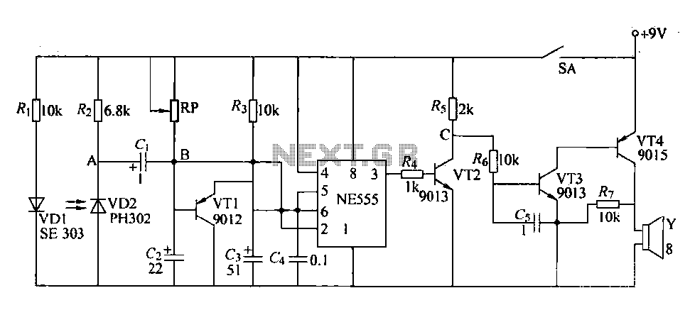
The circuit is designed to detect clogging in a wheat planter by utilizing light-emitting diodes (LEDs) and photodiodes. When the light path is obstructed by particles, the photodiode receives less light, causing the resistance of VD2 to increase. This...
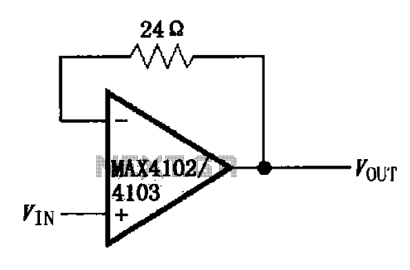
The MAX4102/4103 unity gain buffer circuit is illustrated in the figure. This circuit incorporates a small resistor (24 ohms) positioned in the feedback loop of the amplifier, which forms a unity gain buffer. Additionally, it achieves a maximum bandwidth...
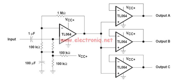
This audio distribution electronic project circuit diagram is designed using the TL064 or TL06 operational amplifiers and some other common electronic parts. The audio distribution circuit utilizes TL064 or TL06 operational amplifiers, which are quad op-amps known for their low...
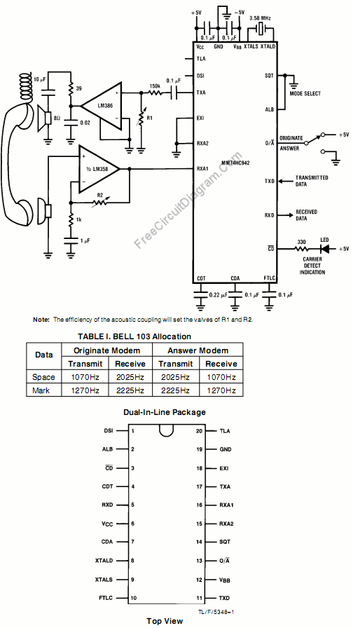
This circuit utilizes the MM74HC942, a single-chip low-speed modem that is compatible with the Bell 103 standard. The Bell 103 modem circuit operates at a baud rate of 300. The MM74HC942 is a versatile integrated circuit designed for low-speed data...
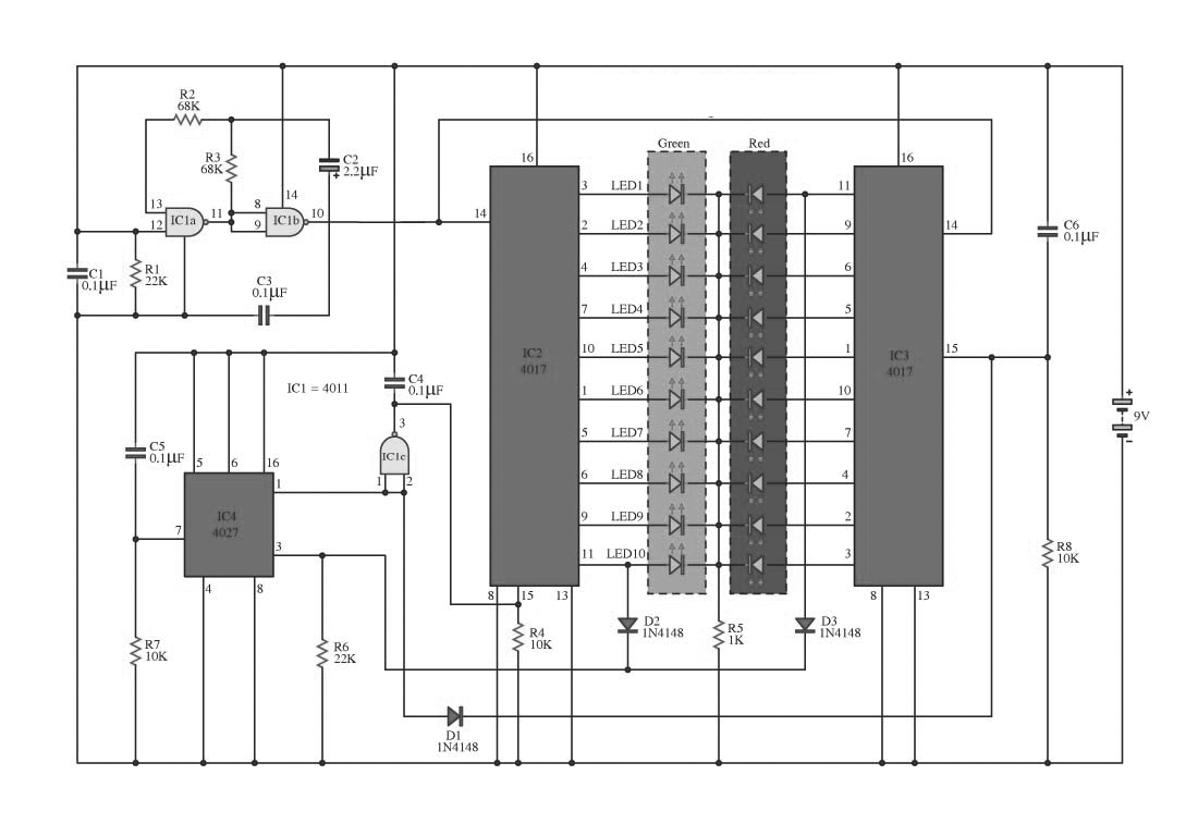
This circuit operates on alternating two colors using a 2-color LED with a built-in 3-pin configuration. It alternates the glow of each LED until the base, switching between two colors. The circuit comprises a NAND gate IC, two 10-counter...
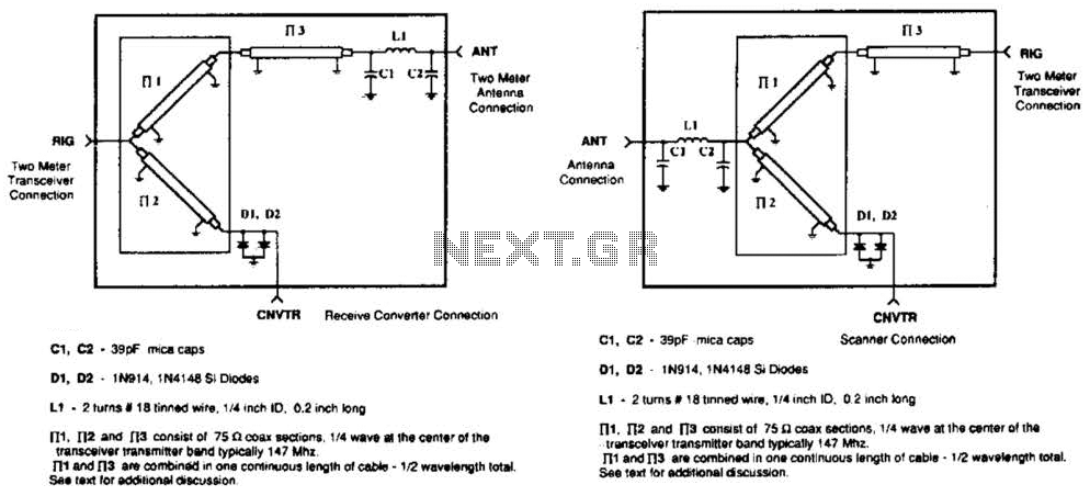
A pair of diodes and a quarter-wave transmission line are utilized as an automatic TR switch. D1 and D2 conduct during transmit periods, short-circuiting the scanner input. In this mode, the quarter-wave line appears as an open circuit. In...