
Zener Diode Testers

The circuit design begins with the 555 Timer IC configured in astable mode, which generates a continuous square wave output. The frequency of oscillation can be adjusted by varying the resistors and capacitors connected to the timer. This output is fed into the primary winding of the LT700 transformer, which steps up the voltage significantly. The choice of a transformer with a primary impedance of 1K and a secondary impedance of 8 ohms is crucial for achieving the desired high voltage output.
The transformer, when energized, produces an AC output at the secondary winding. When the transformer is connected in reverse, it generates approximately 120 volts AC, which is sufficient for testing zener diodes rated up to 50VDC. The AC output is then directed through a rectifying diode, specifically the 1N4004, which converts the AC voltage to pulsating DC.
To smooth out the pulsating DC, a 2.2µF capacitor is employed. It is important that this capacitor is rated for at least 150 VDC to handle the peak voltage without failure. The capacitor filters the rectified output, providing a more stable DC voltage to the zener diode under test.
For the zener diode testing functionality, the circuit includes a multimeter set to measure DC voltage. The zener diode is connected in parallel with the multimeter. A load current switch is integrated into the circuit to allow for testing at two different current levels: 1 mA or 2 mA DC. This feature is essential, as it enables the user to assess the zener diode's performance under different load conditions. A properly functioning zener diode will maintain a constant voltage reading on the multimeter, confirming its operational integrity.
This circuit serves as an effective tool for evaluating zener diodes, ensuring that they meet specified voltage ratings, while also providing a clear and practical method for users to conduct their tests safely and efficiently.Using a single 555 Timer IC and a small transformer to generate a high voltage, this circuit will test zener diodes of voltage ratings up to 50VDC. The 555timer is used in the astable mode, the output at pin3 drives a small audio transformer such as the LT700.
This has a primary impedance of 1K and a secondary impedance of 8 ohms. Used in reverse the unloaded ac voltage is around 120volts ac. This is rectified by the 1N4004 diode and smoothed by the 2. 2u capacitor which MUST be rated at 150 VDC. The zener under test is measured with a multimeter set to DC volts as shown. The load current switch enables the zener to be tested at 1 or 2mA DC. The rectified DC load, but a good zener should maintain the reading on the volt meter. 🔗 External reference
Related Circuits
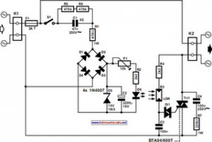
The following circuit illustrates an Automatic Light Dimmer Circuit Diagram utilizing a 1N4007 diode. Features include integration within a wall-mounted box. The Automatic Light Dimmer Circuit is designed to adjust the brightness of a light source automatically based on ambient...
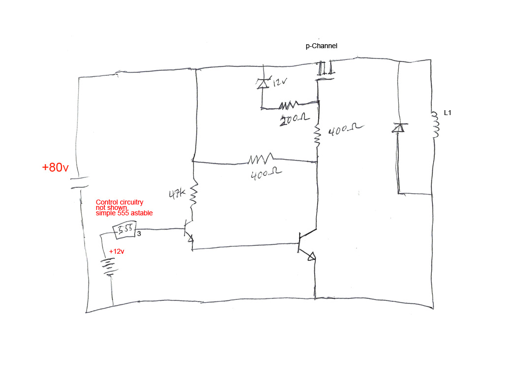
The circuit's premise involves powering an L1 coil with square pulses. A freewheeling diode is included to manage the back EMF field collapse, thereby protecting the circuitry. Previous experiments indicated that using an N-channel MOSFET on the high side...
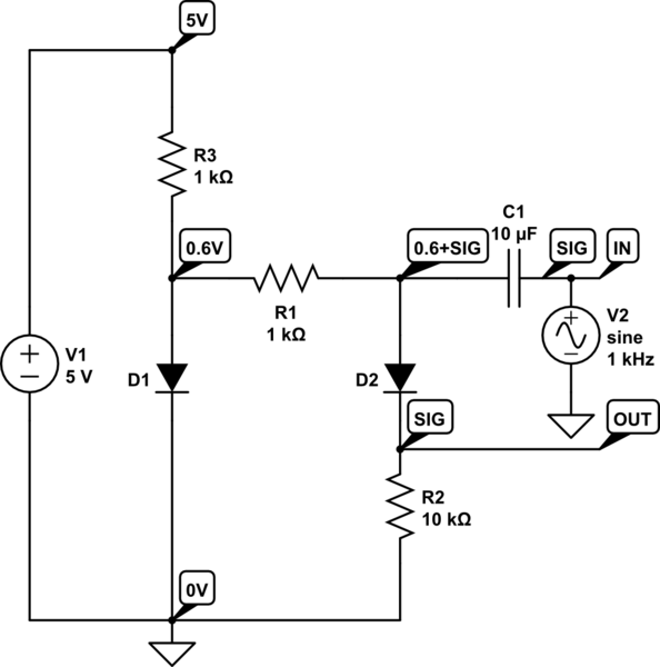
D1 compensates for the forward voltage drop of D2 by providing a 0.6V bias. The +5V is an external source. D1, R1, and R3 create a 0.6V bias on the capacitor's other side, allowing a positive signal swing to...
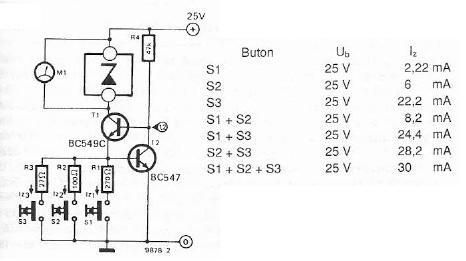
The electronic scheme provided can be used to design a Zener diode tester utilizing a few electronic components. This Zener tester, in conjunction with a multimeter, allows for the precise measurement of the threshold voltage of a Zener diode....
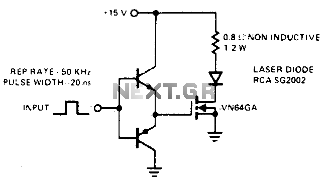
This drive is capable of supplying the laser diode with 10 ampere pulses lasting 20 ns. With a 0% duty cycle, the repetition rate is 50 kHz. A complementary emitter-follower configuration is utilized as a driver. Switching speed is...
Currently, the most commonly available headphones have an impedance ranging from 2 to 32 ohms. This relatively low value renders them unsuitable for certain designs. However, with some clever modifications, these headphones can be effectively utilized in such applications....