
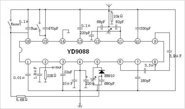
TDA7088T fm radio receiver circuit
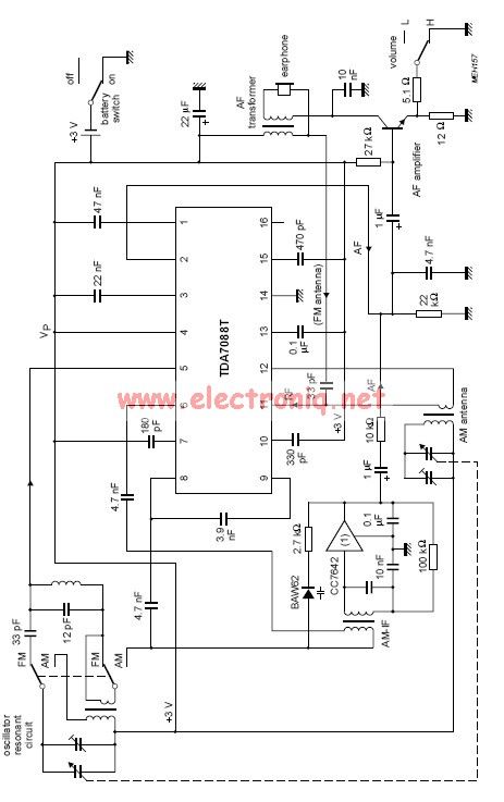
The TDA7088 is designed for use in various applications, particularly in FM radio receivers. The frequency-locked loop (FLL) system is crucial as it enables the circuit to maintain a stable frequency output, which is essential for demodulating the incoming FM signals. The intermediate frequency of 70 kHz is a standard value that allows for effective filtering and amplification of the received signal.
To ensure proper operation, the TDA7088 requires a stable power supply. A 3-volt battery cell is a common power source, making the circuit suitable for portable applications. Alternatively, a regulated power supply can be utilized to provide a consistent voltage, enhancing the performance and reliability of the circuit.
The schematic of the TDA7088 typically includes several key components. These may consist of resistors and capacitors that form the necessary filters and gain stages for the FLL. The circuit may also include external components for tuning and adjusting the frequency response, allowing users to optimize performance based on specific requirements.
In summary, the TDA7088 is a versatile integrated circuit that effectively utilizes a frequency-locked loop system to achieve stable reception of FM signals, powered by either a 3-volt battery or a regulated power supply. Its design is suitable for a range of electronic applications, particularly in the field of radio communications.TDA7088 contains a frequency-locked-loop (FLL) system with an Intermediate Frequency (IF) of about 70 kHz. For supplying this circuit we can use an 3 volts battery cell or a regulated power supply. 🔗 External reference
Related Circuits
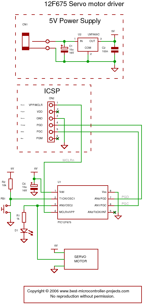
The following circuit illustrates a servo motor driver. This circuit is based on the 12F675 IC. Features include Timer 0 timing and a single control line. The servo motor driver circuit utilizing the 12F675 integrated circuit (IC) is designed to...
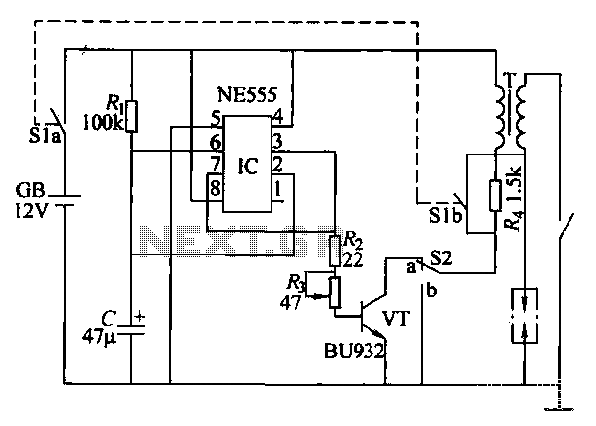
This paragraph describes an easy car alarm circuit that utilizes fewer components and is simple to produce. The circuit consists of an automobile anti-theft alarm system based on the NE555 timer, a power switch (VT), and a switch (S2),...
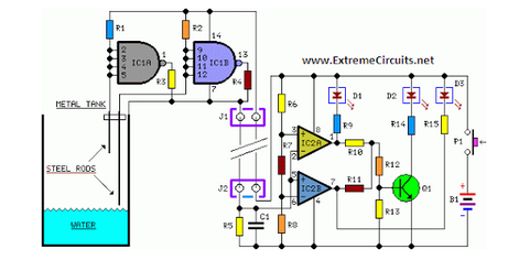
Simple two-wire remote monitoring unit with a three-LED level display, powered by a 9V battery. The entire project was developed at the request of a friend. The remote monitoring unit is designed to provide a straightforward solution for level indication...
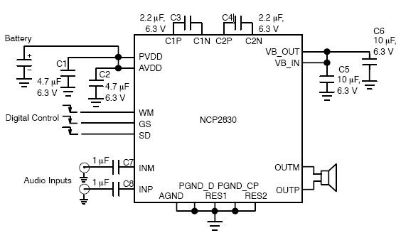
The NCP2830 audio power amplifier features high-quality audio performance with a total harmonic distortion plus noise (THD+N) of 0.04%. It offers low noise with a signal-to-noise ratio (SNR) of up to 100 dB and optimizes overall system efficiency, achieving...
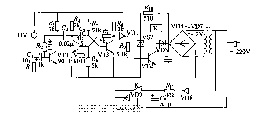
Cook in advance to open the door with a coal stove; before using the fire, it should be strong. This is an automatic door opening device that can automatically open the door before the regular homeowner, eliminating the need...
Zilog's Z8 Encore XP F1680 Series features a highly optimized set of capabilities specifically designed for stepper motor microstepping control. Key features of the Z8 Encore! XP F1680 include: an 11 MHz internal oscillator, two analog comparators, a 10-bit...