
Diode tester using PIC 16F84
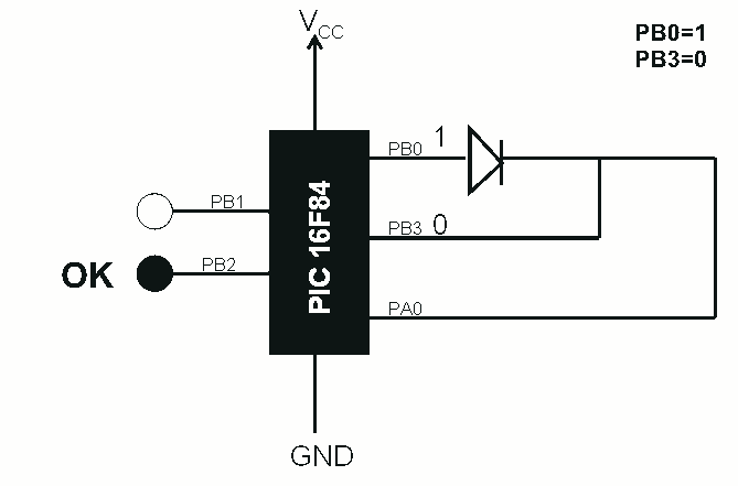

The described circuit utilizes a PIC 16F84 microcontroller to function as a diode tester, facilitating a straightforward method for assessing the health of diodes. The microcontroller is configured to read the status of the diode through its GPIO pins, specifically PB0, PB3, and PA0.
During the testing procedure, the microcontroller sets PB0 to a logical high ("1") and PB3 to a logical low ("0"). This configuration allows for the testing of the diode's forward bias condition. If the diode is functioning correctly, PA0 will read a logical high ("1"), indicating that the diode is conducting. Conversely, if PA0 reads a logical low ("0"), it indicates a fault in the diode.
The microcontroller's firmware is programmed to respond to the readings from PA0 by controlling two LEDs: a green LED and a red LED. When PA0 is high ("1"), the green LED is illuminated, signaling that the diode is operational. If PA0 is low ("0"), the red LED lights up, indicating a defective diode.
The testing can also be performed in a continuous mode by reversing the states of PB0 and PB3, setting PB0 to "0" and PB3 to "1". This allows the microcontroller to assess the diode under reverse bias conditions. The same logic applies: a high reading on PA0 indicates a good diode, while a low reading indicates a failure.
This circuit can be implemented on a breadboard or a custom PCB, with all necessary components including the PIC 16F84 microcontroller, resistors for current limiting on the LEDs, and the diodes to be tested. Proper power supply connections must be made to ensure the microcontroller operates within its specified voltage range. This design provides a practical and efficient method for testing diodes in various applications, making it a valuable tool for both hobbyists and professionals in electronics.This is a simple use of the PIC 16F84 about a diode tester. Test procedure : We set «1» to PB0 and «0» to PB3. If diode is ok and opens, then at PA0 we have «1». If PA0 is «0», then the the diode has problem. With the program we manage what the PIC will do in each situation . If PA0 is «1», green led lights wich means that the diode is OK and if PA0 is «0» red led is lighting and the diode is problematic Test continuous as follows: We give «0» at PB0 and «1» to PB3. If diode is OK and opens, then at PA0 is «1». If PA0 is «0», then diode has problem. If PA0 is «1», green led lights that means that diode is OK and if PA0 is «0» the red diode is lights that means the the diode is problematic. 🔗 External reference
Related Circuits
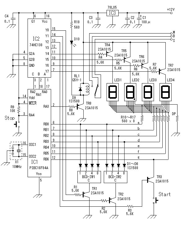
The choice of material to read or drive is the definition of three digits (Bit), RA0, 1,2 PORTA of the PIC at the entrance of 74HC138A. To select a material for reading or driving an output of 78HC138 is...
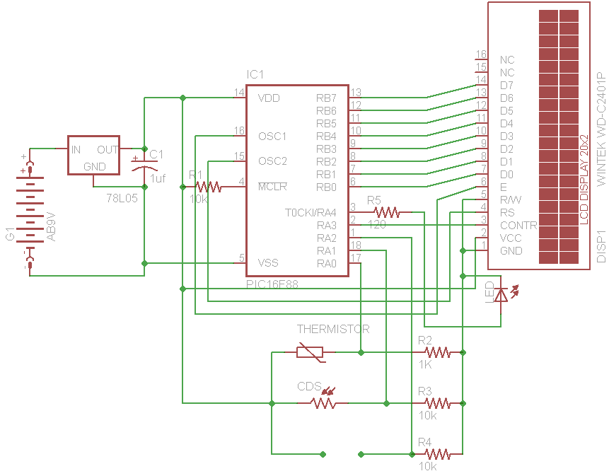
The initial concept for this project involves interfacing the WINTEK WD-C2401P LCD panel with a PIC microcontroller. The intention is to incorporate several ADC readings to provide useful information on the LCD. PORTB on the PIC serves as the...
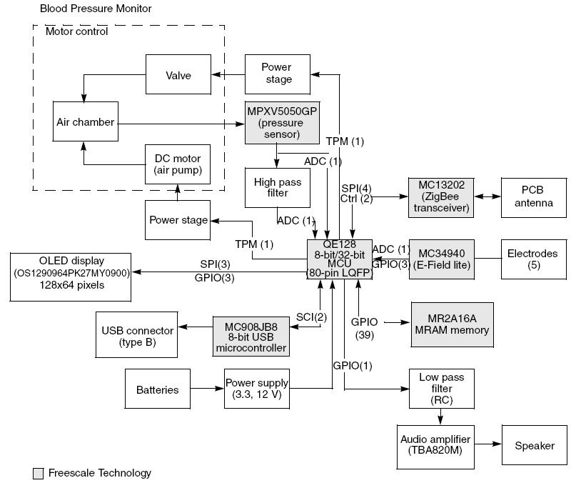
This article demonstrates the implementation of a system capable of measuring arterial blood pressure values. The arterial blood pressure measurement system typically consists of several key components, including sensors, signal processing units, and display interfaces. The primary sensor used in...
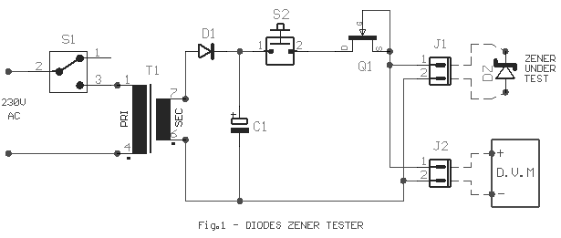
Frequently, there are situations where the need arises to utilize a Zener diode, yet the operational voltage is unknown. Often, the characteristics or type inscribed on the diode are not legible. Zener diodes are essential components in electronic circuits, primarily...
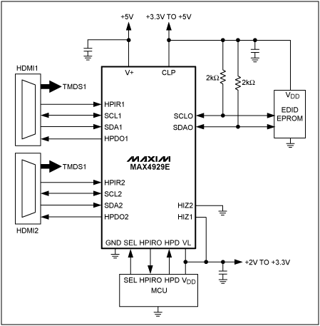
This application note outlines the functionality of the MAX4929E, which manages the switching of all low-frequency signals (LoF) required for a 2:1 HDMI/DVI switch while providing high-level ESD protection for all external lines. It also details how the MAX4929E...

The circuit utilizes the BA1404 integrated circuit from ROHM Semiconductors. The BA1404 is a monolithic FM stereo modulator that incorporates a stereo modulator, FM modulator, and RF amplifier circuitry. This FM transmitter operates within the frequency range of 76...