
How to Design a Blood Pressure Monitor BPM Using the Flexis QE128 Family from Freescale
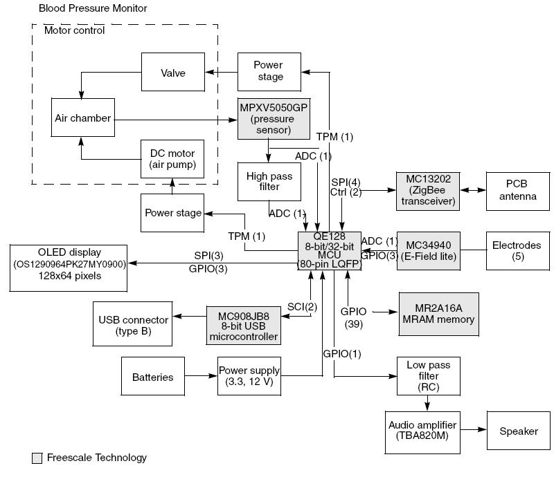
The arterial blood pressure measurement system typically consists of several key components, including sensors, signal processing units, and display interfaces. The primary sensor used in such systems is a pressure transducer, which converts the mechanical pressure exerted by blood flow into an electrical signal. Common types of pressure transducers include piezoelectric and capacitive sensors, each with specific characteristics suitable for medical applications.
Once the pressure transducer captures the blood pressure data, the signal is often weak and requires amplification. An operational amplifier (op-amp) circuit can be employed for this purpose, enhancing the signal strength while maintaining accuracy. The output from the op-amp is then subjected to analog-to-digital conversion (ADC) to facilitate digital processing.
Microcontrollers or digital signal processors (DSPs) play a crucial role in interpreting the digital signal. They can implement algorithms to calculate systolic and diastolic blood pressure values based on the detected waveforms. These algorithms may also include filtering techniques to eliminate noise and improve measurement reliability.
The processed data can then be displayed on a user interface, which may consist of an LCD or LED display. Additionally, the system can be designed to log data for further analysis or transmit it wirelessly to a connected device, such as a smartphone or computer, for remote monitoring.
Power management is also an essential aspect of the design, ensuring that the system operates efficiently, especially in portable applications. Battery management circuits may be incorporated to provide adequate power supply while optimizing energy consumption.
Overall, the design and implementation of an arterial blood pressure measurement system involve a multidisciplinary approach, integrating principles from electronics, signal processing, and biomedical engineering to achieve accurate and reliable measurements.This article shows how to implement a system that can measure arterial blood pressure values 🔗 External reference
Related Circuits
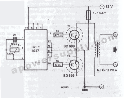
The inverter circuit features the CMOS 4047 as its primary component, converting a 12V DC voltage to a 220V AC voltage. The 4047 operates as an astable multivibrator. A symmetrical rectangular signal is generated at pins 10 and 11,...
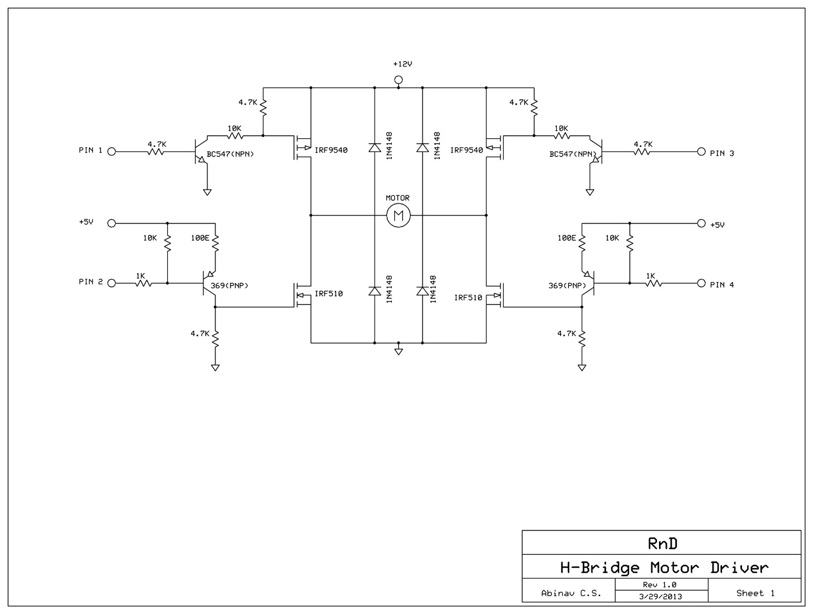
This post discusses the construction of an H-Bridge Motor Driver circuit using simple MOSFETs and transistors. The primary feature of this H-Bridge is its ability to drive a motor in both directions. An H-Bridge is a circuit that allows...
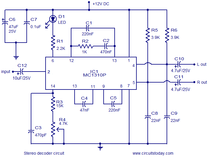
A simple FM stereo decoder circuit utilizing the MC1310P integrated circuit (IC). It operates at 12V and provides a channel separation of 40dB, making it suitable for stereo FM receivers. The FM stereo decoder circuit based on the MC1310P IC...
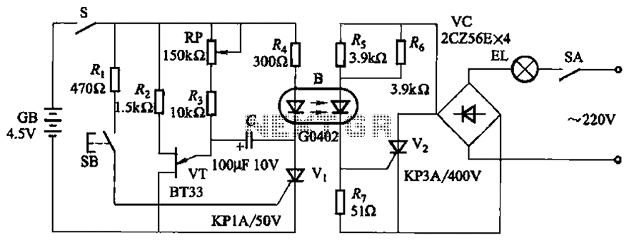
The circuit illustrated in Figure 2-48 consists of two configurations. Configuration 2-48 (a) operates using a 4.5V battery, while configuration 2-48 (b) employs AC capacitors to reduce the voltage supply. In configuration 2-48 (a), the delay time is influenced...
This circuit is designed for children's entertainment and can be installed on bicycles, battery-powered cars, motorcycles, as well as models and various games and toys. When switch SW1 is positioned as indicated in the circuit diagram, it generates the...
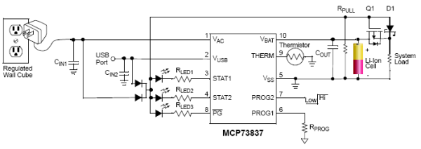
Designing a Li-Ion Battery Charger with Load Sharing MCP73837. Batteries frequently serve as the primary energy source for portable electronic devices. Although these devices rely on batteries, portable consumer electronics such as GPS devices and multimedia players often draw...