
Count Down Timer with PIC16F84A

More:
Prevention of short circuit through the breakers PORTB BCD
Because through the contacts of BCD switches may be shorted pins of PORTB when it acts as output (driving), have been placed in preventive circuit pathways to prevent flow of current.
Pull up Operation
Since the BCD switches on this circuit give reasonable '0 'in closed contacts, to identify the microprocessor has the entrance to each leg to be used consistently logical '1'. Internal Pull-up operation is applied only when the situation in the PORTB pins made from output, input, and if you specify zero '0 'in place of the registrar RPBI OPTION. If the PORTB output serves as the pull-up function does not.
At the stop button of the timer is connected to PORTA added external resistor Pull-up, because this function is only supported on the feet of PORTB.
Relay Output
At the foot of RA3 PORTA is connected to a relay coil, a switched contact, where you can drive any secondary low power device. Each leg of the PIC can provide power in the range of 25-mA. If the relay used in the circuit for the power consumed by the coil is 23-mA, which is very close to the limit. Therefore to avoid possible destruction of the PIC to drive the relay is not directly but through a transistor can provide current in the range of 150-mA.
Timing Circuit
For the timing of the processor used a ceramic filter (Resonator) or 10MHz crystal and two 22pF ceramic capacitors
Feeder circuit
The IC3 stabilize the voltage from 12VDC to 5VDC and capacitors to smooth and filter. Since the consumption of the circuit is too low a stabilizer of about 100mA is enough. The LED Display and looks like it is constantly lit, actually lit one at a time so that the power consumed is relatively small. For the relay mentioned above, so the table below you can see the consumption of the circuit LED Display 7 segments: 50mA A switched relay contact: 25mA Balance circuit: 10mA
The described circuit is a microcontroller-based system utilizing a PIC microcontroller interfaced with a 74HC138A demultiplexer to manage multiple input and output devices. The configuration uses three bits from PORTA (RA0, RA1, RA2) to select which of the multiple outputs is active, ensuring that only one output is activated at any time to avoid conflicts. The outputs are connected to PORTB, which is managed through a combination of input and output states, controlled by the microcontroller's firmware.
To prevent short circuits when the BCD switches are used as inputs, the circuit incorporates protective pathways that mitigate the risk of current flow through the pins of PORTB. This design consideration is crucial for maintaining the integrity of the microcontroller and the overall system.
The BCD switches are designed to provide a logical '0' when closed. To ensure reliable operation, internal pull-up resistors are utilized, allowing the microcontroller to read a logical '1' when the switches are open. This functionality is contingent on the configuration of the RPBI register, which defines the operational mode of the PORTB pins.
A stop button is connected to PORTA, with an external pull-up resistor added to enhance the reliability of the input signal. This is particularly important as the pull-up function is limited to PORTB pins in this design.
A relay is connected to RA3 of PORTA, allowing control of secondary low-power devices. Since the output current from each PIC pin is limited to 25 mA, a transistor (2SA1015) is employed to drive the relay, which requires 23 mA for its coil. This method ensures that the microcontroller operates within safe limits, as the transistor can handle higher current levels (up to 150 mA).
The timing circuit employs a ceramic resonator or a 10 MHz crystal oscillator, with two 22 pF ceramic capacitors to stabilize the clock signal for the microcontroller, ensuring accurate timing operations.
The power supply circuit includes an IC3 voltage regulator that steps down the voltage from 12 VDC to 5 VDC, with additional capacitors for filtering and smoothing the output. The low overall power consumption of the circuit allows for a 100 mA regulator to be sufficient. The LED display utilizes a multiplexing technique, where only one segment is lit at any given time, reducing overall power consumption. The current draw for various components is specified, indicating 50 mA for the seven-segment LED display, 25 mA for the relay, and 10 mA for the balance circuit, ensuring efficient operation of the entire system.The choice of material to read or drive is the definition of three digits (Bit), RA0, 1,2 PORTA of the PIC at the entrance of 74HC138A. To select a material for reading or driving an output of 78HC138 is '0 '(Low), forcing the transistor (2SA1015) to conduct and thus is the material with the feet of PORTB.
This function ensures that there will never be found simultaneously connected to PORTB two materials, since the remaining transistors are off. Switches BCD (inputs), the start button (input) and LED Display (outputs) are controlled solely by the pins RB0 - RB7 of PORTB.
Depending on what material is selected and modified the state of PORTB (If it is input or output). Prevention of short circuit through the breakers PORTB BCD Because through the contacts of BCD switches may be shorted pins of PORTB when it acts as output (driving), have been placed in preventive circuit pathways to prevent flow of current. Pull up Operation Since the BCD switches on this circuit give reasonable '0 'in closed contacts, to identify the microprocessor has the entrance to each leg to be used consistently logical '1'.
Internal Pull-up operation is applied only when the situation in the PORTB pins made from output, input, and if you specify zero '0 'in place of the registrar RPBI OPTION. If the PORTB output serves as the pull-up function does not. At the stop button of the timer is connected to PORTA added external resistor Pull-up, because this function is only supported on the feet of PORTB.
Relay Output At the foot of RA3 PORTA is connected to a relay coil, a switched contact, where you can drive any secondary low power device. Each leg of the PIC can provide power in the range of 25-mA. If the relay used in the circuit for the power consumed by the coil is 23-mA, which is very close to the limit.
Therefore to avoid possible destruction of the PIC to drive the relay is not directly but through a transistor can provide current in the range of 150-mA. Timing Circuit For the timing of the processor used a ceramic filter (Resonator) or 10MHz crystal and two 22pF ceramic capacitors Feeder circuit The IC3 stabilize the voltage from 12VDC to 5VDC and capacitors to smooth and filter.
Since the consumption of the circuit is too low a stabilizer of about 100mA is enough. The LED Display and looks like it is constantly lit, actually lit one at a time so that the power consumed is relatively small. For the relay mentioned above, so the table below you can see the consumption of the circuit LED Display 7 segments: 50mA A switched relay contact: 25mA Balance circuit: 10mA
🔗 External reference
Related Circuits
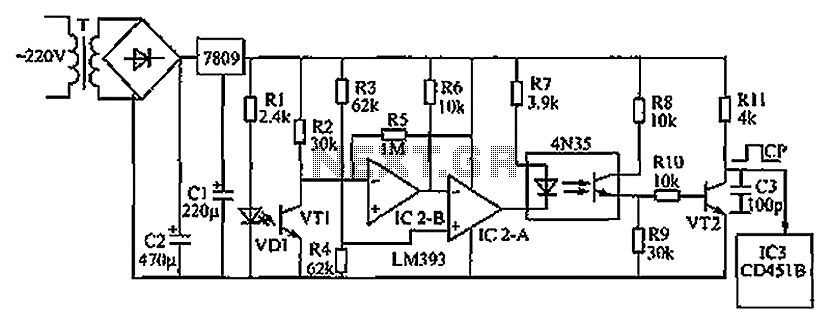
The circuit depicted in the figure operates as follows: when the phototransistor VT1 detects infrared light emitted by the infrared light-emitting diode, it enters a conductive state. This action causes the inverting input of comparator IC2-B, connected to pin...
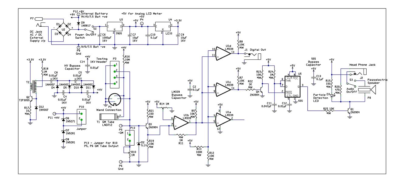
With the recent events at the Fukushima Dai-ichi nuclear power plant, it would be interesting to build a Geiger Counter and connect it to a NerdKit for interfacing with a computer. An article detailing the building process is available,...
The figure illustrates a preset outage timer circuit designed for an electric cooker. The timing range of the circuit extends from 1 hour to 12 hours, adjustable via a potentiometer (PR). The timing mode operates on a counting basis,...
This circuit measures the distance covered during a walk. The hardware is located in a small box that can be slipped into a pants pocket. The display is designed such that the leftmost display, D2 (the most significant digit),...
Hardware is located in a small box slipped in pants pocket and the display is conceived in the following manner: the leftmost display D2 (the most significant digit) shows 0 to 9 Km. and its dot is always on...
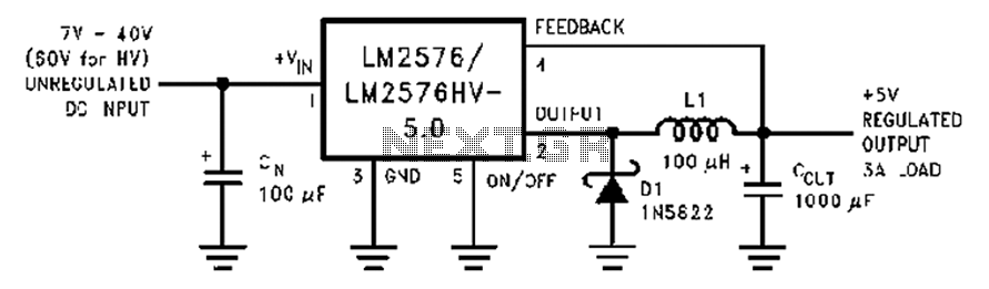
A wide range of 7 to 40V DC-DC step-down circuit that converts input voltage to 5V. This circuit operates as a buck converter, designed to efficiently reduce a higher DC voltage (ranging from 7V to 40V) to a stable output...