
Diode Tube
The diode tube, as described, serves as a fundamental component in early electronic circuits, showcasing the principles of electron flow and voltage application. The filament circuit operates by heating the filament, which emits electrons through thermionic emission, a phenomenon first observed by Edison. The emitted electrons travel toward the positively charged plate, creating a flow of current. The schematic representation highlights the dual nature of the circuit, emphasizing the interdependence of both the filament and plate circuits.
In practical applications, the plate voltage is critical as it influences the rate of electron emission from the filament. A higher plate voltage increases the electric field strength, enhancing the attraction of electrons from the filament to the plate, thereby increasing the plate current. Conversely, if the plate voltage is insufficient, the emission of electrons is reduced, resulting in lower plate current.
The ammeter placed in the plate circuit is essential for measuring the plate current, providing insights into the operational characteristics of the diode. This measurement is crucial for understanding the efficiency and performance of the diode tube in various applications, such as amplification and rectification in early radio and audio equipment.
Overall, the evolution from Edison’s incandescent bulb to Fleming’s valve illustrates the progression of electronic technology, laying the groundwork for modern diodes and semiconductor devices that continue to shape the field of electronics today.The diode tube we are about to study is really Edison`s old incandescent bulb with the plate in it. Diode means two elements or two electrodes, and refers to the two parts within the glass container that make up the tube. Within a few years after the discovery of the Edison effect, scientists had learned a great deal more than Edison knew at the t
ime of his discovery. By the early 1900s, J. J. Thomson in England had discovered the electron. Marconi, in Italy and England, had demonstrated the wireless, which was to become the radio. The theoretical knowledge of the nature of electricity and things electrical was increasing at a rapid rate. J. A. Fleming, an English scientist, was trying to improve on Marconi`s relatively crude wireless receiver when his mind went back to Edison`s earlier work.
Before learning about Fleming`s valve, the forerunner of the modern diode, let`s look at Edison`s original circuit. This time, however, we`ll draw it as a schematic diagram, using the symbol for a diode instead of a cartoon-like picture.
(The schematic shown below). Note that this is really two series circuits. The filament battery and the filament itself form a series circuit. This circuit is known as the filament circuit. The path of the second series circuit is from one side of the filament, across the space to the plate, through the ammeter and battery, then back to the filament. This circuit is known as the plate circuit. You will note that a part of the filament circuit is also common to the plate circuit. This part enables the electrons boiled from the filament to return to the filament. No electron could flow anywhere if this return path were not completed. The electron flow measured by the ammeter is known as plate current. The voltage applied between the filament and plate is known as plate voltage. 🔗 External reference
Related Circuits
.jpg)
The design data for a 3TF7 replacement is based on information from "The Ballast Tube Handbook" by Jacobi and the R-390x part list. The 3TF7 outputs approximately 12 Vac with an input voltage of around 26 Vac. The ballast...
To get a low output impedance I needed to use quite a high step-down ratio (20:1); after all, the amplifier may be used with headphones of lower impedance than the 300 Ohms of the HD600. The output valve is...
I want to start building a tube compressor for my bass guitar. I found a compressor schematic with two ECC83 tubes, but it seems too old. The design of a tube compressor for musical instruments, particularly for bass guitars, typically...
The only schematic of this amplifier known is the one obtained from Song at Canadian HiFi Online. The schematic in question represents the electronic configuration of a specific amplifier model. This schematic is crucial for understanding the circuit's operation, including...
This is the unedited version of the article "Improved Anode-Circuit Parasitic-Suppression For Modern Amplifier-Tubes," which was published on page 36 of the October 1988 issue of QST. A subsequent discussion on this topic appeared in the September and October...
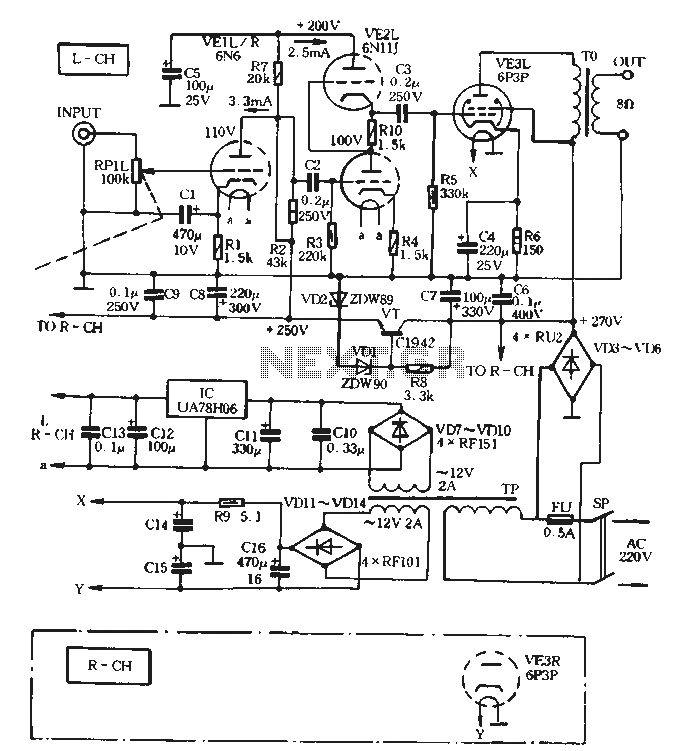
The VE1 preamplifier utilizes a low muscle, low resistance double triode 6N6 configuration, with separate halves for the left and right audio channels. The design operates within the CPI framework. It promotes the use of high-level VE2 household low...