
Tube 3TF7 Current Regulator
.jpg)
The circuit design for the 3TF7 replacement involves careful selection of components to ensure compatibility with the R-390 and R-390A receivers. The ballast serves a critical role in regulating the heater voltage supplied to the tubes, which is essential for stable operation. The choice of resistor R1 is crucial, as it limits the current to a safe level while maintaining the desired heater voltage. The use of a copper plate not only provides a robust mounting surface for the components but also aids in thermal management. The integration of a mica spacer for IC1 ensures that heat dissipation is optimized, protecting sensitive components from excessive temperatures.
The testing methodology employed provides confidence in the performance of the prototype, as it mimics real operating conditions. The measurement of voltage drops across the resistive components allows for precise current evaluation, which is vital for ensuring that the circuit operates within the specified parameters. The design reflects an understanding of the thermal and electrical characteristics of the components involved, enabling reliable performance in the intended application. Overall, this detailed approach to the design and testing of the 3TF7 replacement demonstrates a thorough understanding of the requirements for successful integration into the R-390 and R-390A systems.Here are design data for a 3TF7 replacement. Design was based upon the information found in The Ballast Tube Handbook` by Jacobi and on the descriptive field of the R-390x part list: Actually, according to the voltage charts of R-390x receivers, the 3TF7 gives approximately 12 Vac at its output, with an input voltage around 26 Vac. The ballast output is wired to the series detailed below: Giving a look to the voltage distribution along the above paths for both the R-390 and the R390A we find different data as resulting from the voltage/resistance tables in the respective technical manuals: The secondary winding nominal voltage, entering into the 3TF7 ballast, is set at 26 Vac for the R-390 and at 25. 2 Vac for the R-390A. Well, we have at the output of the ballast 11. 3 Vac, or 14. 7 V drop, for the R-390 and 12 Vac, or 13. 2 V drop, for the R-390A. It was common practice to operate low power tubes at reduced heater voltage for a more stable behavior through their life.
From the tables of the R-390 we find 5. 3 volts across the heater of V508, the BFO oscillator, and 5. 7 volts across V701, the VFO oscillator, plus a 0. 3 V drop across the RF filtering inductor. In the R-390A voltage drops across the heaters of the two tubes are the same, 6 volts each, but we find no drop on the RF filter coil. The inconsistency of different readings for two series connected heaters can derive from tolerances in their resistance values, as we should think of 3TF7 and of the same controlled heaters as temperature depending resistors.
Data given for 3TF7, 8. 6 V drop at 310 mA, probably refer to its cold resistance at the start. Since oscillator tubes operate with heater drops around 6 VAC, the current flow must be under the nominal value of 300 mA. Measuring heater current at different voltages on several 6BA6 and 6BA6W samples, I found the following values: Now we have enough data to refine the design.
The circuit is given below in figure 3. Assuming an average heater voltage of 5. 7 volts for R-390 and of 6. 0 volts for R-390A, the value of the limiting resistor R1 should be centered for a current of about 285 mA. The circuit was assembled on a small copper plate, 20 by 60 mm, 2. 5 mm thick, obtained pressing a copper water tubing. The plate was soldered to pins 1 and 6 of a noval plug. IC1 was mounted with a mica spacer in the coolest place, close to the base. The bridge was riveted to the plate, while other components were mounted using small teflon press-fit stand-offs.
A picofuse can be used for F1 if available. Otherwise the fusible link can be easily removed from a 20 mm glass cartridge and soldered directly into the circuit. Before the use in the R-390A receiver, the prototype was thoroughly tested with a load very similar to the real one, obtained connecting two 6BA6W heaters and a small 0.
5 ohm resistor in series. Voltage drop across the 0. 5 ohm resistor was measured with a Fluke 8922A true rms digital voltmeter, to evaluate the current flowing in the heaters. Moving the supply voltage in the range of 25. 2 VAC +/-10%, the measured rms current in the circuit was 286mA +/-2%. The prototype was then operated inside a R-390A, with no appreciable difference against the original ballast.
Obviously I could not run full tests to the temperature and voltage limits specified for the receiver. Anyway I am quite sure that very few people today operate their R-390 or R-390A at 75 C ambient temperature.
🔗 External reference
Related Circuits
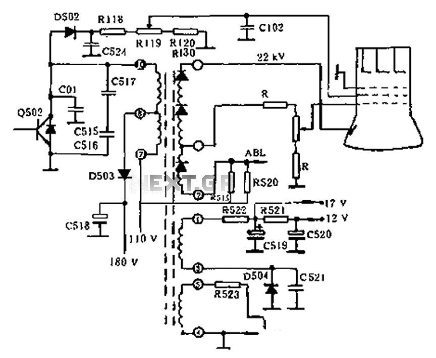
The circuit diagram of the Swallow CS37-2 type color TV illustrates the feeding tube configuration. The filament voltage is supplied by the line flyback transformer, with a current-limiting resistor R523. The accelerating voltage is managed by D502, which rectifies...
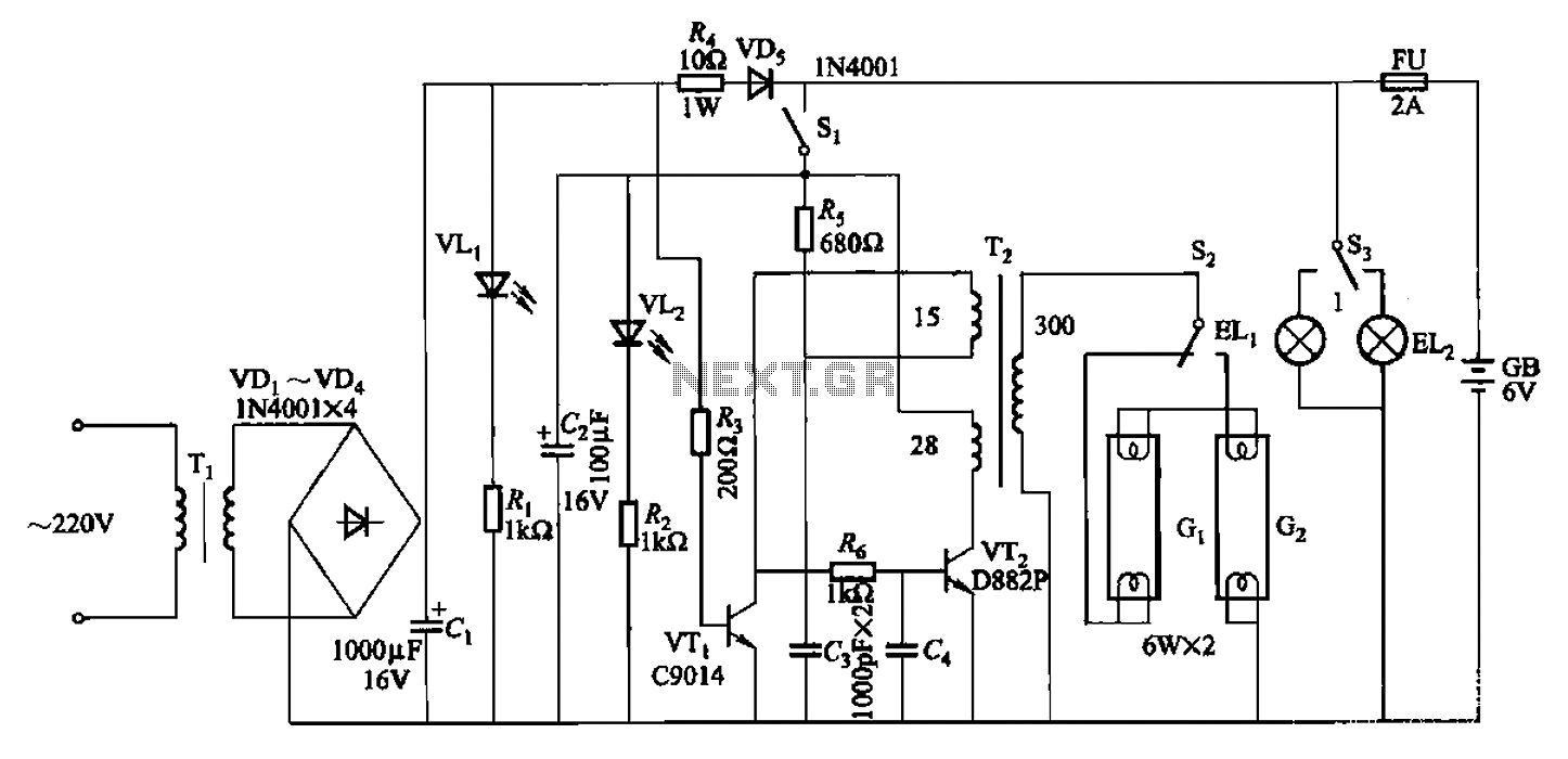
The 786A multi-functional double-tube fluorescent emergency circuit is illustrated in Figure 2-129. This circuit shares similarities with Figure 2-125. The 786A multi-functional double-tube fluorescent emergency circuit is designed to provide illumination during power outages or emergencies. It utilizes two fluorescent...
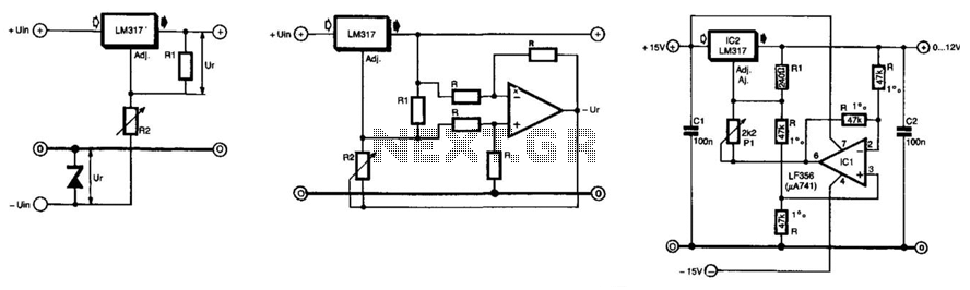
The unique feature of this regulator is that the output voltage can be adjusted down to 0 V. The regulation is provided by an integrated regulator type LM317. Typically, in supplies that can be adjusted to 0 V, this...
The current feedback operational amplifier maintains a consistent bandwidth even when the open-loop gain is altered. This characteristic makes it particularly suitable for applications in video signal amplification and the driving circuits of video cables. The accompanying diagram illustrates...
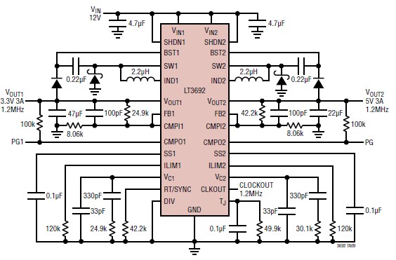
A 3.3V and 5V DC-DC converter circuit design project utilizing the LT3692 dual tracking regulator. The LT3692 is a highly efficient dual-output DC-DC converter designed for applications requiring both 3.3V and 5V outputs. This integrated circuit can provide a regulated...
The circuit presented here uses linear shunt regulation. Simply spoken, it burns off all excess energy from the panel, keeping output voltage constant. At times when the solar panel output is equal or greater than the load, and the...