
Diodeless Rectifier Circuit
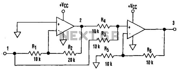
The second amplifier, configured as a non-inverting summing amplifier, combines the inverted negative signal from the first amplifier with the original input signal. The overall output results in the traditional waveform characteristic of full-wave rectification. Despite the constraint on input signal amplitude, which must remain below VCC/2, this circuit can be effectively employed in various applications.
This circuit design utilizes a pair of operational amplifiers to achieve full-wave rectification without the need for diodes, which can introduce forward voltage drops and limit the precision of the output. The first op amp operates as an inverting amplifier, where the input signal is inverted and amplified by a factor of 2. This configuration ensures that negative input voltages are accurately represented, while positive voltages are clipped to zero, effectively preparing the signal for summation.
The second op amp is configured as a non-inverting summing amplifier, which takes the output from the first op amp and adds it to the original input signal. This summation process is crucial, as it combines the inverted negative signal with the positive portion of the original signal, resulting in a full-wave rectified output. The output waveform produced by this arrangement closely resembles that of traditional full-wave rectifiers, providing a clear representation of both the positive and negative halves of the input signal.
The design's limitation regarding the input signal amplitude, which must be less than VCC/2, is an important consideration for practical applications. This restriction ensures that the op amps operate within their linear range, maintaining signal integrity and preventing distortion. The circuit's high precision and ability to handle high-frequency signals make it suitable for various electronic applications, including audio processing, signal conditioning, and instrumentation, where accurate rectification is essential. Overall, this configuration highlights the utility of op amps in achieving effective signal processing in single-supply environments. It`s common knowledge that when working with single-supply op amps, implementing simple functions in a bipolar signal environment can be difficult. Sometimes additional op amps and other electronic components are required. Taking that into consideration, can any advantage be attained from this mode The answer lies in this simple circuit (A).
Requiring no diodes, the circuit is a high-precision full-wave rectifier with a liigli-frequency limitation equalling that of the op amps themselves. Look at the circuit`s timing diagram (B) to see the principle of operation. The first amplifier rectifies negative input levels with an inverting gain of 2 and turns positive levels to zero.
The second amp, a noninverting summing amplifier, adds the inverted negative signal from the first amplifier to the original input signal. The net result is the traditional waveform produced by full-wave rectification. In spite of the limitation on the input signal amplitude (it must be less than VCCJZ), this circuit can be useful in a variety of setups.
🔗 External reference
Related Circuits
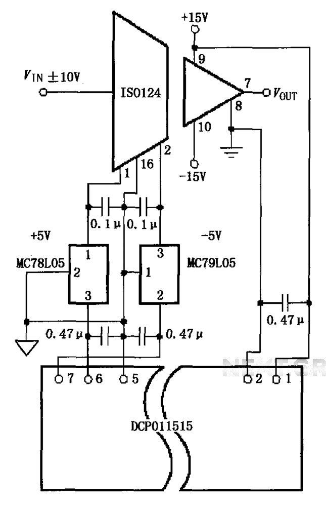
The circuit depicted in the figure includes the ISO124 and MC78L05 components, along with an external regulator, MC79L05, and the DCP011515, which collectively enhance the power supply rejection ratio (PSR) of the circuit. The input signal, VIN (maximum swing...
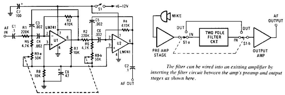
This variable-frequency audio bandpass filter is constructed using two 741 operational amplifiers connected in cascade. The two 741 op amps are configured as identical RC active filters and are cascaded to enhance selectivity. The filter's tuning range spans from...
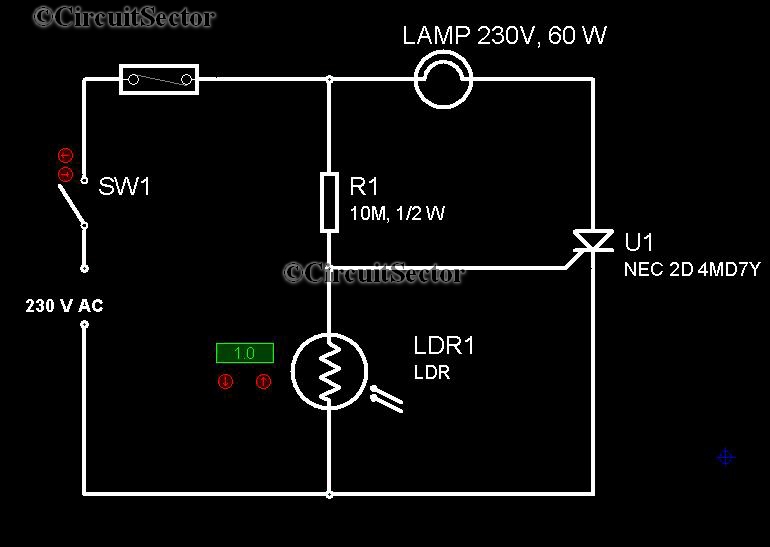
It is very convenient to automatically light a lamp in our absence during the evening when it gets dark. This automatic night lamp circuit can be utilized to illuminate staircase lights, porch lights, etc., automatically using a domestic power...
The circuit illustrated in Figure 3-2 features a loop reactor governor that incorporates a series reactor. The reactor can be constructed using a TV choke and is designed to be approximately 3mm in height. It utilizes a strength wire...
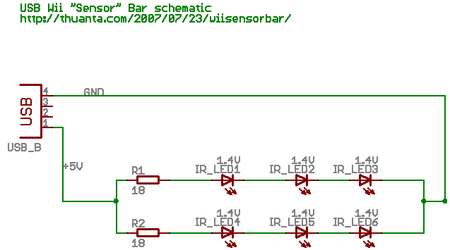
The following circuit illustrates the Wii "Sensor" Bar Project Circuit Diagram. Features include a series of infrared LEDs positioned at both ends of the bar, which emit infrared light. The Wii Sensor Bar is a crucial component for the Wii...
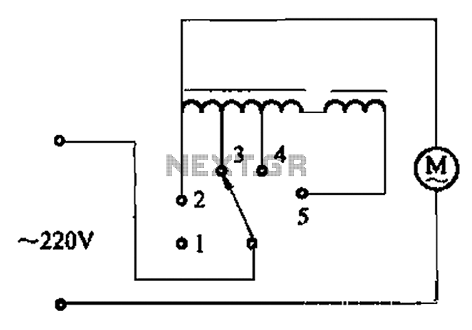
This AC motor speed controller can handle most universal type (brushed) AC motors and other loads up to about 250W. It works in much the same way as a light dimmer circuit; by chopping part of the AC waveform...